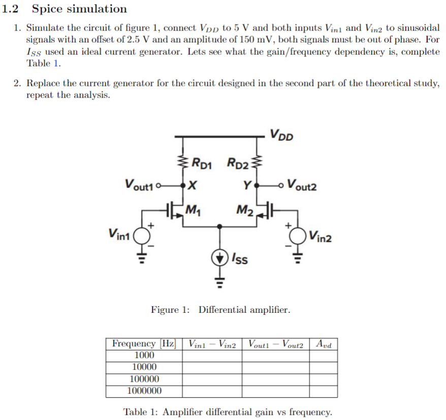
1.2 Spice simulationSimulate the circuit of figure 1 , connect VDD to 5 V and both inputs Vin1 and Vin2 to sinusoidal signals with an offset of 2.5 V and an amplitude of 150 mV, both signals must be out of phase. For ISS used an ideal current generator. Lets see what the gain/frequency dependency is, complete Table 1. Replace the current generator for the circuit designed in the second part of the theoretical study, repeat the analysis. Figure 1: Differential amplifier. Table 1: Amplifier differential gain vs frequency.