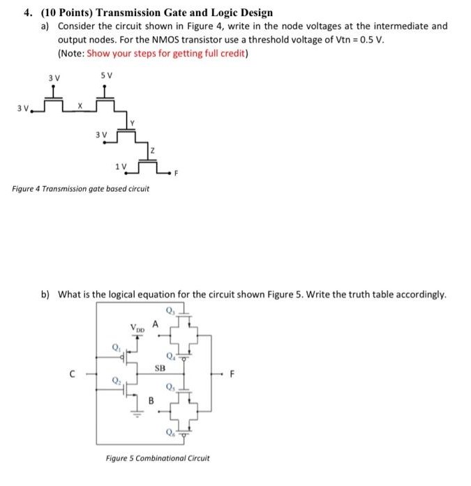
(10 Points) Transmission Gate and Logic Design a) Consider the circuit shown in Figure 4, write in the node voltages at the intermediate and output nodes. For the NMOS transistor use a threshold voltage of Vtn = 0.5 V. (Note: Show your steps for getting full credit) Figure 4 Transmission gate based circuit b) What is the logical equation for the circuit shown Figure 5. Write the truth table accordingly. Figure 5 Combinational Circuit
(10 Points) Transmission Gate and Logic Design a) Consider the circuit shown in Figure 4, write in the node voltages at the intermediate and output nodes. For the NMOS transistor use a threshold voltage of Vtn = 0.5 V. (Note: Show your steps for getting full credit) Figure 4 Transmission gate based circuit b) What is the logical equation for the circuit shown Figure 5. Write the truth table accordingly. Figure 5 Combinational Circuit

Image text
  1. (10 Points) Transmission Gate and Logic Design a) Consider the circuit shown in Figure 4, write in the node voltages at the intermediate and output nodes. For the NMOS transistor use a threshold voltage of Vtn = 0.5 V . (Note: Show your steps for getting full credit)
Figure 4 Transmission gate based circuit b) What is the logical equation for the circuit shown Figure 5. Write the truth table accordingly. Figure 5 Combinational Circuit

Detailed Answer