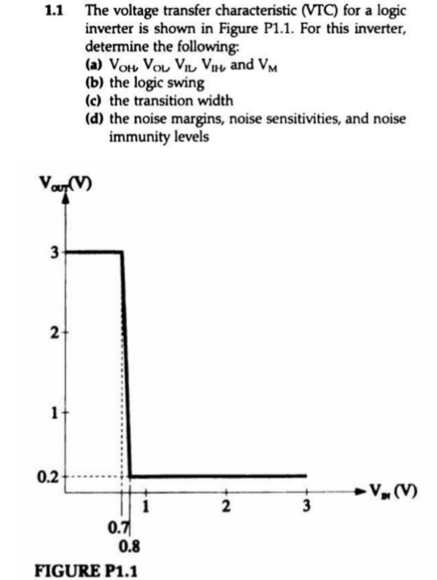
16.17 The voltage-transfer characteristic of a particular logic inverter is modeled by three straight-line segments in the manner shown in Fig. 16.13. If VIL = 1.1 V, VIH = 1.2 V, VOL = 0.3 V, and VOH = 1.5 V, find: (a) the noise margins (b) the value of VM (c) the voltage gain in the transition region Figure 16.13 Voltage-transfer characteristic of an inverter. The VTC is approximated by three straight-line segments. Note the four parameters of the VTC (VOH, VOL, VIL, and VIH) and their use in determining the noise margins (NMH and NML).

You'll get a detailed, step-by-step and expert verified solution.
 Work With Experts to Reach at Correct Answers