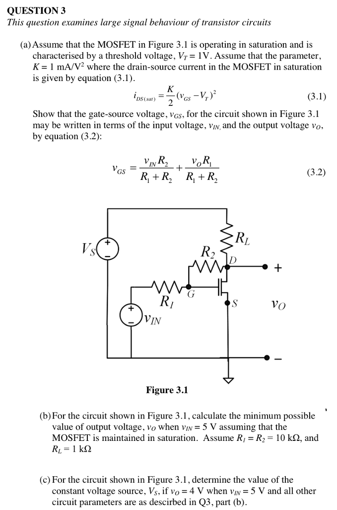
(a) Assume that the MOSFET in Figure 3.1 is operating in saturation and is characterised by a threshold voltage, VT = 1 V. Assume that the parameter, K = 1 mA/V2 where the drain-source current in the MOSFET in saturation is given by the usual expression: iDS = K2(vGS−VT)2 Calculate the output voltage, vo, for the circuit shown in Figure 3.1 when vIN = 2.5 V, Vs = 10 V, and R = 1 kΩ. The correct solution should satisfy both conditions necessary for the device to operate in saturation. Figure 2.1 [10 marks] (b) For the circuit in Figure 2.1, calculate the small signal voltage gain of the circuit, Av, at the operating point defined by the numerical values of part (a). Assume the input and output voltages include small signal components, vin and vout respectively. VIN and Vout correspond to the constant DC components of the input and output voltage from part (a). vIN = VIN +vin vOUT = VOUT +vout Av = vout vin [10 marks] (c) Determine the small signal output impedance at the terminals labelled a and b for the circuit shown in Figure 3.1 and at the operating point defined by the numerical values of part (a). [10 marks]
![(a) Assume that the MOSFET in Figure 3.1 is operating in saturation and is characterised by a threshold voltage, VT = 1 V. Assume that the parameter, K = 1 mA/V2 where the drain-source current in the MOSFET in saturation is given by the usual expression: iDS = K2(vGS−VT)2 Calculate the output voltage, vo, for the circuit shown in Figure 3.1 when vIN = 2.5 V, Vs = 10 V, and R = 1 kΩ. The correct solution should satisfy both conditions necessary for the device to operate in saturation. Figure 2.1 [10 marks] (b) For the circuit in Figure 2.1, calculate the small signal voltage gain of the circuit, Av, at the operating point defined by the numerical values of part (a). Assume the input and output voltages include small signal components, vin and vout respectively. VIN and Vout correspond to the constant DC components of the input and output voltage from part (a). vIN = VIN +vin vOUT = VOUT +vout Av = vout vin [10 marks] (c) Determine the small signal output impedance at the terminals labelled a and b for the circuit shown in Figure 3.1 and at the operating point defined by the numerical values of part (a). [10 marks]](https://www.doubtrix.com/uploads/editor/3475428305cJOidAHSIp.jpg)

You'll get a detailed, step-by-step and expert verified solution.
 Work With Experts to Reach at Correct Answers