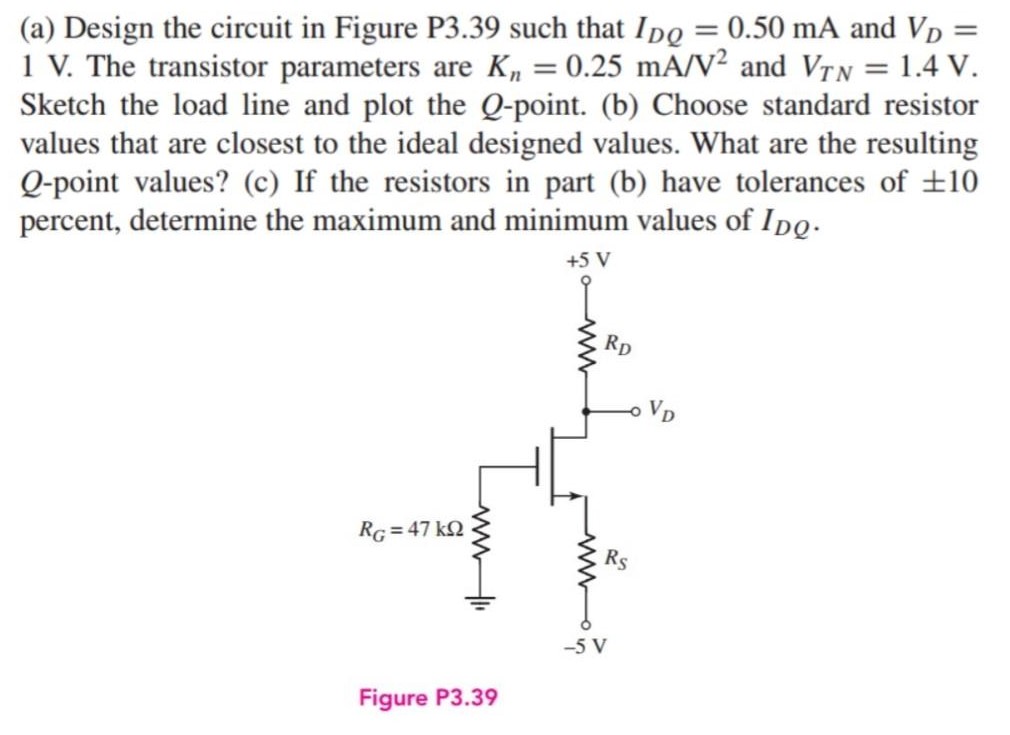
(a) Design the circuit in Figure P3.39 such that IDQ = 0.50 mA and VD = 1 V. The transistor parameters are Kn = 0.25 mA/V2 and VTN = 1.4 V. Sketch the load line and plot the Q-point. (b) Choose standard resistor values that are closest to the ideal designed values. What are the resulting Q-point values? (c) If the resistors in part (b) have tolerances of ±10 percent, determine the maximum and minimum values of IDQ. Figure P3.39
(a) Design the circuit in Figure P3.39 such that IDQ = 0.50 mA and VD = 1 V. The transistor parameters are Kn = 0.25 mA/V2 and VTN = 1.4 V. Sketch the load line and plot the Q-point. (b) Choose standard resistor values that are closest to the ideal designed values. What are the resulting Q-point values? (c) If the resistors in part (b) have tolerances of ±10 percent, determine the maximum and minimum values of IDQ. Figure P3.39

Image text
(a) Design the circuit in Figure P3.39 such that I D Q = 0.50 m A and V D = 1 V . The transistor parameters are K n = 0.25 m A / V 2 and V T N = 1.4 V . Sketch the load line and plot the Q -point. (b) Choose standard resistor values that are closest to the ideal designed values. What are the resulting Q -point values? (c) If the resistors in part (b) have tolerances of ± 10 percent, determine the maximum and minimum values of I D Q .
Figure P3.39

Detailed Answer