A feedback amplifier circuit is shown in Figure Q4. Figure Q4: Feedback Amplifier (a) What type of feedback topology is used in this amplifier? (b) Redraw the amplifier circuit, replacing the op-amp with the equivalent circuit for this feedback topology. (c) Estimate the current, Io, the feedback gain, Aif in dB, and the amplitude of the AC voltage, vo, when RF = 150 kΩ, R1 = 4.7 kΩ, RL = 820 Ω, and Ii = 40 μAp−p at 1 kHz.
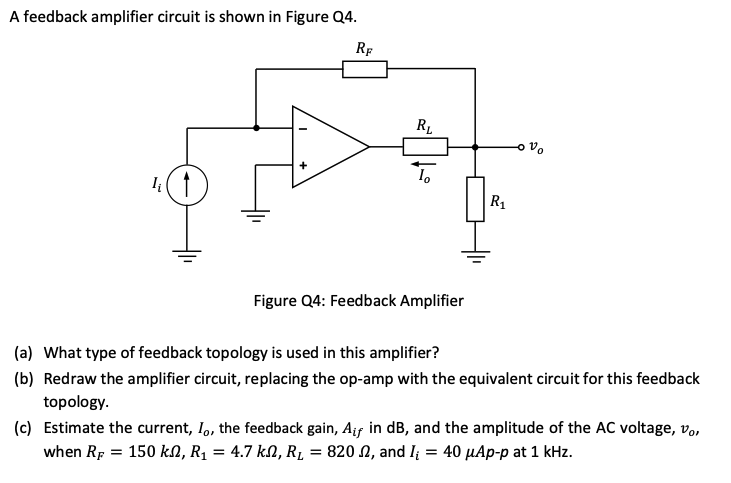
A feedback amplifier circuit is shown in Figure Q4. Figure Q4: Feedback Amplifier (a) What type of feedback topology is used in this amplifier? (b) Redraw the amplifier circuit, replacing the op-amp with the equivalent circuit for this feedback topology. (c) Estimate the current, Io, the feedback gain, Aif in dB, and the amplitude of the AC voltage, vo, when RF = 150 kΩ, R1 = 4.7 kΩ, RL = 820 Ω, and Ii = 40 μAp−p at 1 kHz.

Image text
A feedback amplifier circuit is shown in Figure Q4. Figure Q4: Feedback Amplifier (a) What type of feedback topology is used in this amplifier? (b) Redraw the amplifier circuit, replacing the op-amp with the equivalent circuit for this feedback topology. (c) Estimate the current, I o , the feedback gain, A i f in d B , and the amplitude of the AC voltage, v o , when R F = 150 k Ω , R 1 = 4.7 k Ω , R L = 820 Ω , and I i = 40 μ A p p at 1 k H z .

Detailed Answer