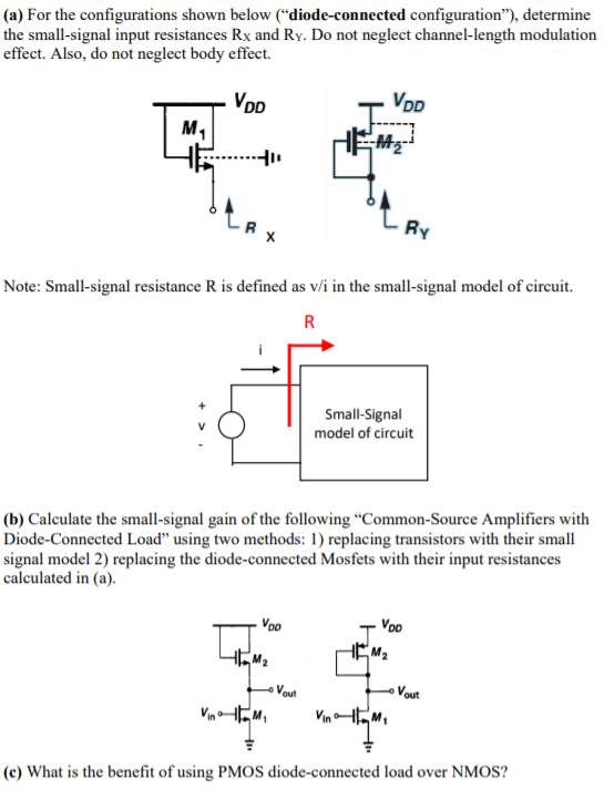
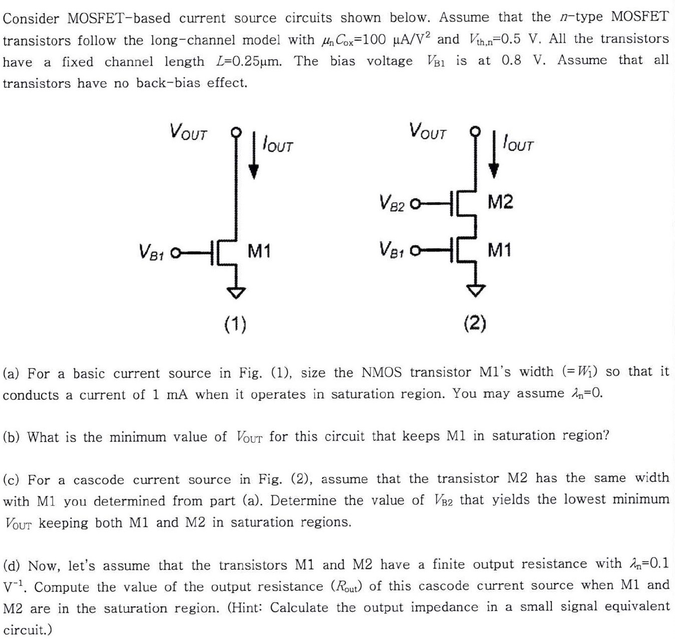
(a) For the configurations shown below ("diode-connected configuration"), determine the small-signal input resistances Rx and RY. Do not neglect channel-length modulation effect. Also, do not neglect body effect. Note: Small-signal resistance R is defined as v/i in the small-signal model of circuit. (b) Calculate the small-signal gain of the following "Common-Source Amplifiers with Diode-Connected Load" using two methods: 1) replacing transistors with their small signal model 2) replacing the diode-connected Mosfets with their input resistances calculated in (a). (c) What is the benefit of using PMOS diode-connected load over NMOS?