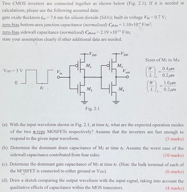
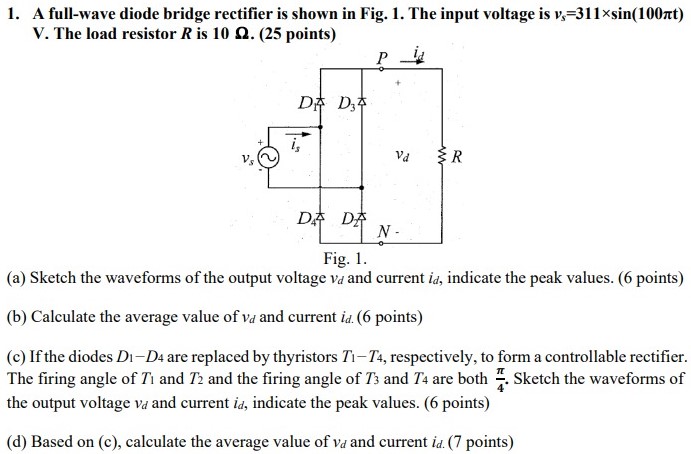
A full-wave bridge rectifier circuit is shown in Fig. 2(a) with a "floating" signal generator and grounded load resistor, which is the most common configuration of this rectifier. Its output waveform appears in Fig. 2 b. Note that the output frequency is twice the input frequency, but the time period T and angular period 2π on the horizontal axis refer to the input waveform. Following a similar development to the halfwave rectifier, the dc output voltage from the full-wave bridge rectifier is given by: Vavg = 1π∫θ1 θ2[Vmsin(θ) − 2Vd]dθ Where, the integration is over half the original waveform's period and the 2Vd term is due to the load current flowing through two diodes. The peak output voltage is vo, peak = Vm − 2Vd. The integration limits are found using Eq. 5 with the angles referred to the original input waveform. θ1 = sin−1(2Vd/Vm) and θ2 = π − θ1 However, the full-wave rectifier's conduction angle must be referred to the output waveform's period, which is half that of the input so φ = 2(θ1−θ2). (a) (b) Fig. 2. (a) Full-wave bridge rectifier circuit and (b) output waveform. Perform the following calculations for the full-wave rectifier in Fig. 2. Put your results in Table 1. a. Determine vo,peak, θ1, and θ2 for the rectifier output waveform of Fig. 2 b. b. Calculate the average (dc) value of vo(t) using Eq. 4 . c. Calculate the conduction angle φ.
![A full-wave bridge rectifier circuit is shown in Fig. 2(a) with a "floating" signal generator and grounded load resistor, which is the most common configuration of this rectifier. Its output waveform appears in Fig. 2 b. Note that the output frequency is twice the input frequency, but the time period T and angular period 2π on the horizontal axis refer to the input waveform. Following a similar development to the halfwave rectifier, the dc output voltage from the full-wave bridge rectifier is given by: Vavg = 1π∫θ1 θ2[Vmsin(θ) − 2Vd]dθ Where, the integration is over half the original waveform's period and the 2Vd term is due to the load current flowing through two diodes. The peak output voltage is vo, peak = Vm − 2Vd. The integration limits are found using Eq. 5 with the angles referred to the original input waveform. θ1 = sin−1(2Vd/Vm) and θ2 = π − θ1 However, the full-wave rectifier's conduction angle must be referred to the output waveform's period, which is half that of the input so φ = 2(θ1−θ2). (a) (b) Fig. 2. (a) Full-wave bridge rectifier circuit and (b) output waveform. Perform the following calculations for the full-wave rectifier in Fig. 2. Put your results in Table 1. a. Determine vo,peak, θ1, and θ2 for the rectifier output waveform of Fig. 2 b. b. Calculate the average (dc) value of vo(t) using Eq. 4 . c. Calculate the conduction angle φ.](https://www.doubtrix.com/uploads/editor/6776072514rhzokOtWGl.png)