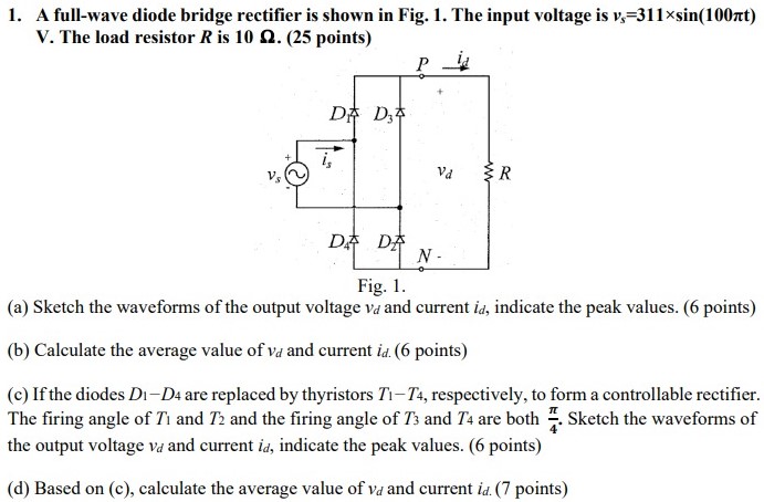
A full-wave diode bridge rectifier is shown in Fig. 1 . The input voltage is vs = 311×sin(100πt) V. The load resistor R is 10 Ω. ( 25 points) Fig. 1. (a) Sketch the waveforms of the output voltage vd and current id, indicate the peak values. (6 points) (b) Calculate the average value of vd and current id. ( 6 points) (c) If the diodes D1−D4 are replaced by thyristors T1−T4, respectively, to form a controllable rectifier. The firing angle of T1 and T2 and the firing angle of T3 and T4 are both π4. Sketch the waveforms of the output voltage vd and current id, indicate the peak values. (6 points) (d) Based on (c), calculate the average value of vd and current id. (7 points)
