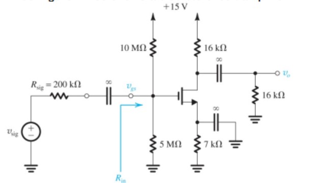
Figure P7.33 shows a discrete-circuit amplifier. The input signal vsig is coupled to the gate through a very large capacitor (shown as infinite). The transistor source is connected to ground at signal frequencies via a very large capacitor (shown as infinite). The output voltage signal that develops at the drain is coupled to a load resistance via a very large capacitor (shown as infinite). All capacitors behave as short circuits for signals and as open circuits for dc. (a) If the transistor has Vt = 1 V, and kn = 4 mA/V2 , verify that the bias circuit establishes VGS = 1.5 V, ID = 0.5 mA, and VD = +7.0 V. That is, assume these values, and verify that they are consistent with the values of the circuit components and the device parameters. (b) Find gm and ro if VA = 100 V. (c) Draw a complete small-signal equivalent circuit for the amplifier, assuming all capacitors behave as short circuits at signal frequencies. (d) Find Rin, vgs/vsig, vo/vgs, and vo/vsig.
