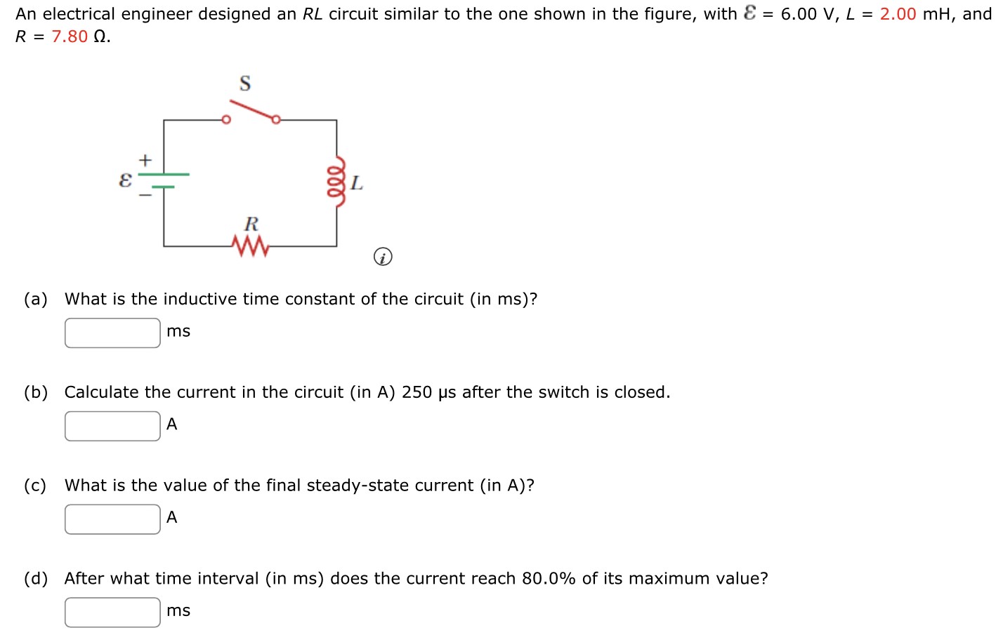
An electrical engineer designed an RL circuit similar to the one shown in the figure, with ε = 6.00 V, L = 2.00 mH, and R = 7.80 Ω (a) What is the inductive time constant of the circuit (in ms)? ms (b) Calculate the current in the circuit (in A) 250 μs after the switch is closed. A (c) What is the value of the final steady-state current (in A)? A (d) After what time interval (in ms ) does the current reach 80.0% of its maximum value? ms