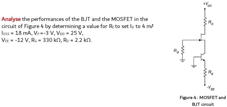
Analyse the performances of the BJT and the MOSFET in the circuit of Figure 4 by determining a value for RE to set ID to 4 mA IDSS = 18 mA, VP = −3 V, VDD = 25 V, VEE = −12 V, RG = 330 kΩ, RD = 2.2 kΩ. Figure 4: MOSFET and BJT circuit
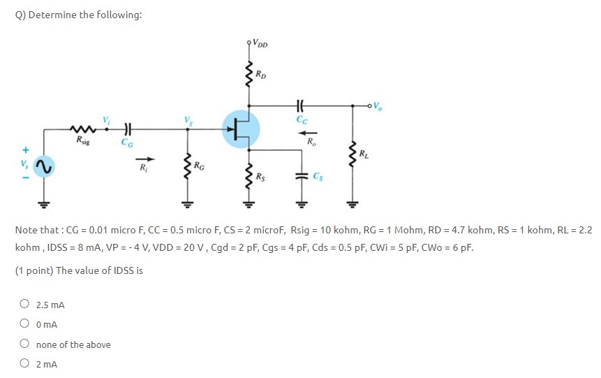
Image text
Analyse the performances of the BJT and the MOSFET in the circuit of Figure 4 by determining a value for to set to

![Question 2 The following parameters have been defined for the MOSFET amplifier circuit shown in Figure 2.1: VDD = 20 V, R1 = 2.2 MΩ, R2 = 1.8 MΩ, RD = 1.5 kΩ. (a) Given that the MOSFET has the parameters K = 0.475 mA/V2 and a turn-on voltage, Vto = 2.1 V, calculate the value of source resistance, Rs, needed to set a DC bias drain current of ID = 4 mA. [6 marks] (b) With Rs set at the value calculated in part (a), determine the value of the drain voltage, VD, and confirm whether or not the MOSFET is operating in the saturation region. [5 marks] (c) If the MOSFET has rd = 10 kΩ, complete the small-signal equivalent model for the amplifier circuit and calculate its input resistance, output resistance, open-circuit gain (i.e., with RL = ∞) and overall gain (when RL = 1 kΩ). [9 marks] Figure 2.1](https://www.doubtrix.com/uploads/editor/2185749880UDRAjiUDlM.png)
![Figure P5-1 shows a common source single transistor MOSFET amplifier utilizing an N-Channel Enhancement Mode MOSFET. The term "common source" refers to the source terminal being shared by both the input circuit and the output circuit. The parameters for the MOSFET and the supply voltage are also given. Hand Analysis P1. In terms of DC bias, determine a value for VGS to set the drain current ID to 5 mA. Also determine a value for RD to set the VDS bias to 6 V. P2. In terms of small-signal parameters, determine the transconductance gm of this amplifier as well as the voltage gain, Av. P3. If vgs is a 0.1 Vpk sinewave at a frequency of 1 kHz [ie. vgs = 0.1sin(2pift)V ] determine an expression for the output voltage vOUT as a function of time. Sketch vIN and vOUT for two complete cycles, including the DC bias for each signal. Simulation P4. Simulate the circuit of Figure P5-1 to verify your hand analysis and create a plot similar to P3 as part of your prelab. Use the virtual MOSFET model in simulation with SPICE parameters VT0 = 1.8 V and KP = 120 mA/V2. (The default values of 100um for W and L will be fine since their ratio equals unity.)](https://www.doubtrix.com/js/ckeditor/filemanager/connectors/php/editor/1695874154-Avjhgifoih.png)