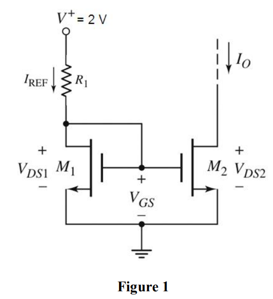
(b) For a MOSFET current source shown in Figure 3, the bias voltages are V+ = 1.5 V and V− = −1.5 V. Transistors are available with the parameters: kn' = 200 μA/V2, VTN = 0.5 V, and λ = 0. Figure 3 (i) Design the circuit such that IREF = 100 μA, IO = 250 μA, and VDS2(sat) = 1 V. [10 Marks] (ii) Calculate the change in output current, dIo and hence the output current Io when VDS2 = 3 V. Let λ = 0.01 V−1.
![(b) For a MOSFET current source shown in Figure 3, the bias voltages are V+ = 1.5 V and V− = −1.5 V. Transistors are available with the parameters: kn' = 200 μA/V2, VTN = 0.5 V, and λ = 0. Figure 3 (i) Design the circuit such that IREF = 100 μA, IO = 250 μA, and VDS2(sat) = 1 V. [10 Marks] (ii) Calculate the change in output current, dIo and hence the output current Io when VDS2 = 3 V. Let λ = 0.01 V−1.](https://www.doubtrix.com/uploads/editor/2253037833BFDIismlOd.jpg)