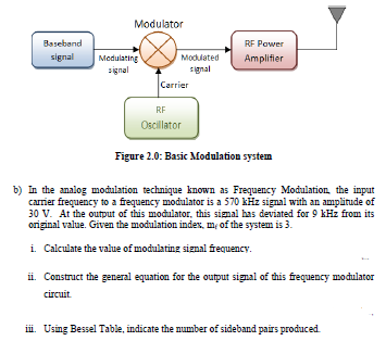
b) In the analog modulation technique known as Frequency Modulation, the input carrier frequency to a frequency modulator is a 570 kHz signal with an amplitude of 30 V. At the output of this modulator, this signal has deviated for 9 kHz from its original value. Given the modulation index, mf of the system is 3. i. Calculate the value of modulating signal frequency. ii. Construct the general equation for the output signal of this frequency modulator circuit. iii. Using Bessel Table, indicate the number of sideband pairs produced. Figure 2.0: Basic Modulation system

![The process of impressing low-frequency information signals onto a high-frequency carrier signal is called modulation. Amplitude modulation (AM) is the process of changing the amplitude of a relatively high frequency carrier signal in proportion with the instantaneous value of the modulating signal. Consider an Amplitude Modulation (AM) wave signal v(t) = [15 + 4sin(44×103 t)]sin(46.5×10⁶ t). i. Determine the type of the AM signal. [2 marks] ii. Calculate the powers of the carrier and side bands in dBm. [4 marks] iii. Draw the power spectrum with a clear label of the frequencies and amplitudes for all the components. [4 marks]](https://www.doubtrix.com/uploads/editor/7221706923axKoxjJseR.jpeg)