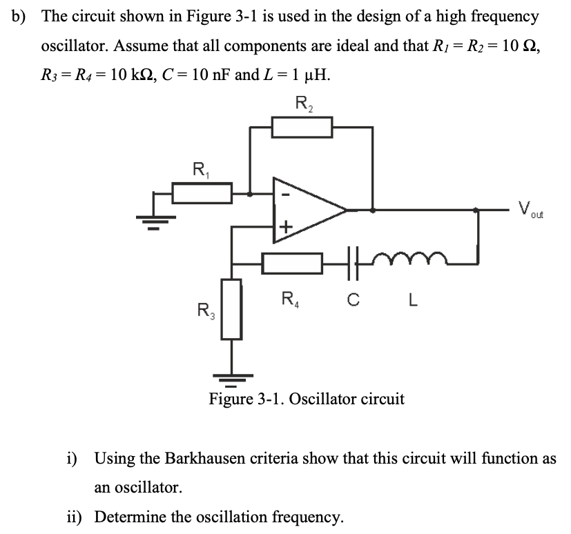
b) The circuit shown in Figure 3-1 is used in the design of a high frequency oscillator. Assume that all components are ideal and that R1 = R2 = 10 Ω, R3 = R4 = 10 kΩ, C = 10 nF and L = 1 μH. Figure 3-1. Oscillator circuit i) Using the Barkhausen criteria show that this circuit will function as an oscillator. ii) Determine the oscillation frequency.

![Figure Q1 shows a common-emitter amplifier. The gain of the transistor Q1 is given by β = 100 , the resistances are given by RS = 500 Ω, RI = 1 MΩ, R2 = 1 MΩ, RC = 10 kΩ, RE = 10 kΩ and RL = 1 kΩ, and the internal capacitances are given by Cμ = 2 pF and Cπ = 20 pF. Assume that the internal resistances rb = 10 Ω, rμ = ∞, ro = ∞ and the external capacitances CS, CE and CL are large. Figure Q1 a) If the supply voltage, VCC, is 12 V, compute the collector current, IC, hybrid- π parameters, gm and rπ for the transistor Ql. [8 Marks] b) Sketch the small-signal equivalent circuit in a form suitable for high frequency analysis. [3 Marks] c) By using Miller's theorem, calculate the internal capacitances C1 and C2. [6 Marks] d) Sketch the small-signal equivalent circuit again which includes the capacitances C1 and C2. [3 Marks] e) Using open-circuit time constant method, calculate the 3 dB upper corner frequency, fH. [5 Marks]](https://www.doubtrix.com/uploads/editor/9277406453JjmioByNud.jpg)