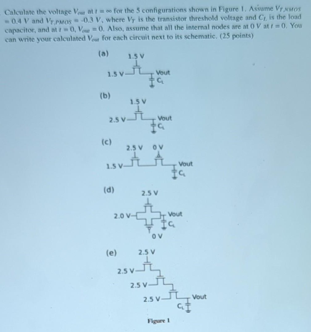
Calculate the voltage Vout at t = oo, for the 5 configurations shown in Figure 1. Assume VT,NMOS = 0.4 V and VT,PMOS = -0.3 V, where VT is the transistor threshold voltage and CL is the load capacitor, and at t = 0, Vout = 0. Also, assume that all the internal nodes are at 0 V at t = 0. You can write your calculated Vout for each circuit next to it

You'll get a detailed, step-by-step and expert verified solution.
 Work With Experts to Reach at Correct Answers