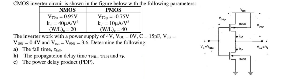
CMOS inverter circuit is shown in the figure below with the following parameters: The inverter work with a power supply of 4 V, VOL = 0 V, C = 15pF, Vout = V10% ? =0.4 V and Vout = V90% = 3.6. Determine the following: a) The fall time, tfall. b) The propagation delay time tPHL, tPLH and tP. c) The power delay product (PDP).

You'll get a detailed, step-by-step and expert verified solution.
 Work With Experts to Reach at Correct Answers