Consider the circuit below where the drain current through M1, M2, and M3 is designed to be 1 mA. Assume VT = 1 V and Kn′ = 2 mA/V2. a) Find the W/L ratio for M2 and the DC voltages at all nodes. b) Draw the small-signal model for the circuit at the operating point you found in part a. Derive an expression for the small-signal gain (A = vo/vi) and evaluate it numerically.
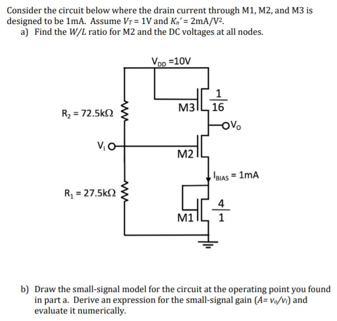
Consider the circuit below where the drain current through M1, M2, and M3 is designed to be 1 mA. Assume VT = 1 V and Kn′ = 2 mA/V2. a) Find the W/L ratio for M2 and the DC voltages at all nodes. b) Draw the small-signal model for the circuit at the operating point you found in part a. Derive an expression for the small-signal gain (A = vo/vi) and evaluate it numerically.

Image text
Consider the circuit below where the drain current through M1, M2, and M3 is designed to be 1 m A . Assume V T = 1 V and K n = 2 m A / V 2 . a) Find the W / L ratio for M2 and the DC voltages at all nodes. b) Draw the small-signal model for the circuit at the operating point you found in part a. Derive an expression for the small-signal gain ( A = v o / v i ) and evaluate it numerically.

Detailed Answer