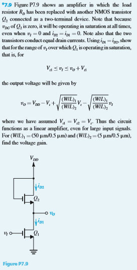
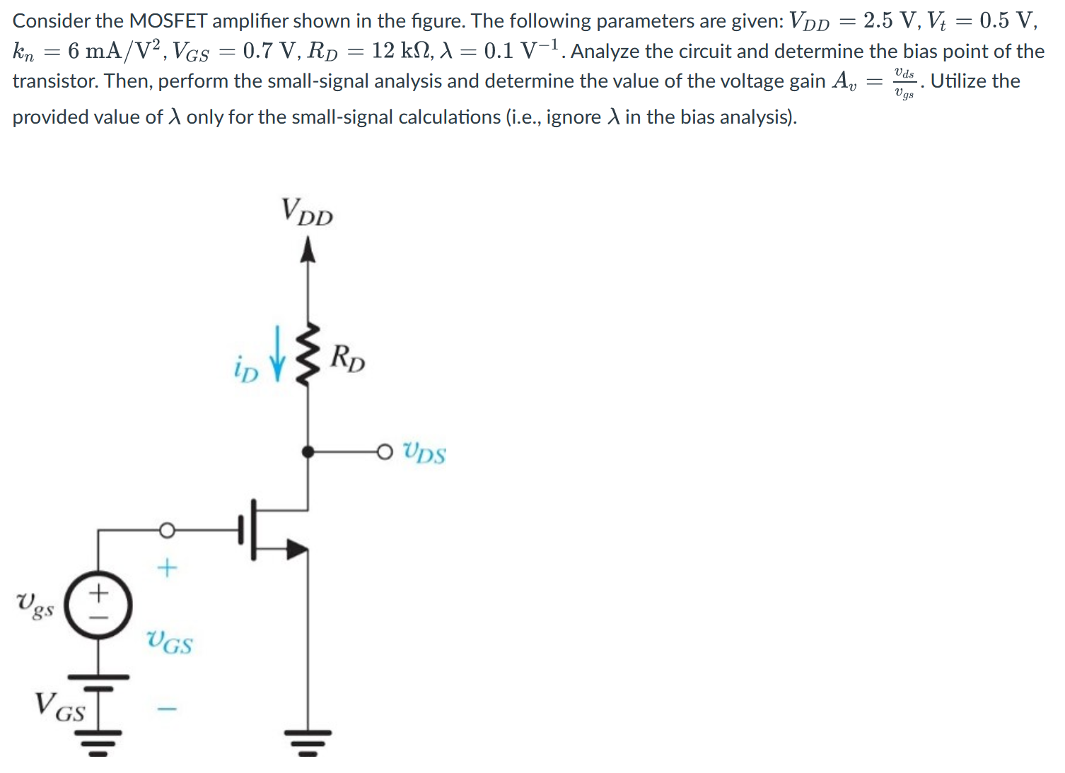
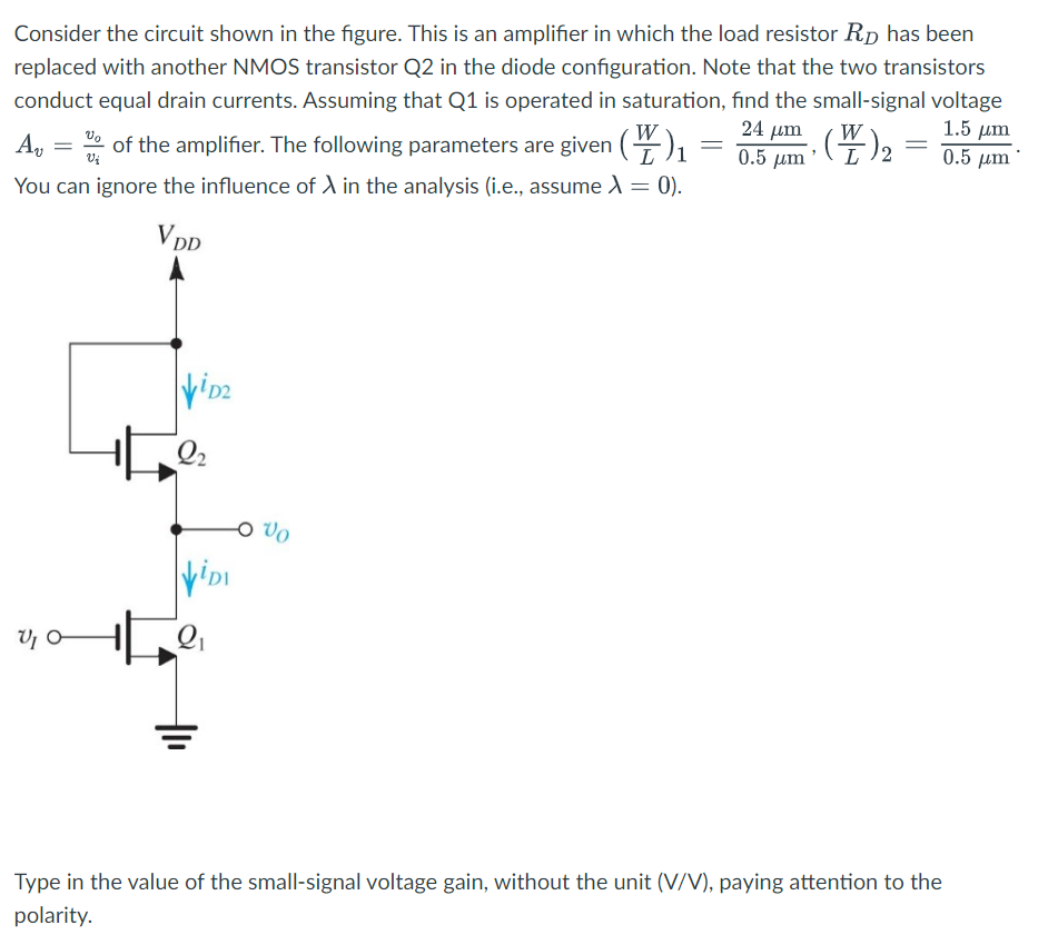
Consider the circuit shown in the figure. This is an amplifier in which the load resistor RD has been replaced with another NMOS transistor Q2 in the diode configuration. Note that the two transistors conduct equal drain currents. Assuming that Q1 is operated in saturation, find the small-signal voltage Av = vo/vi of the amplifier. The following parameters are given (W/L)1 = 24 μm/0.5 μm, (W/L)2 = 1.5 μm/0.5 μm. You can ignore the influence of λ in the analysis (i.e., assume λ = 0). Type in the value of the small-signal voltage gain, without the unit (V/V), paying attention to the polarity.
You'll get a detailed, step-by-step and expert verified solution.
 Work With Experts to Reach at Correct Answers