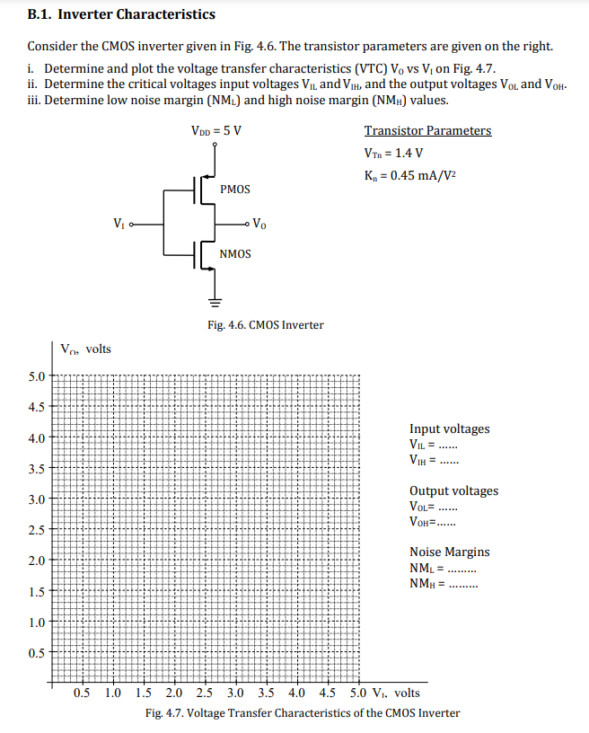
Consider the CMOS inverter given in Fig. 4.6. The transistor parameters are given on the right.
i. Determine and plot the voltage transfer characteristics (VTC) Vo vs Vi on Fig. 4.7.
ii. Determine the critical voltages input voltages VIL and ViIH, and the output voltages VOL and VOH.
ii. Determine low noise margin (NML) and high noise margin (NMH) values
Image text
Consider the CMOS inverter given in Fig. 4.6. The transistor parameters are given on the right.
i. Determine and plot the voltage transfer characteristics (VTC) Vo vs Vi on Fig. 4.7.
ii. Determine the critical voltages input voltages VIL and ViIH, and the output voltages VOL and VOH.
ii. Determine low noise margin (NML) and high noise margin (NMH) values

![Consider a CMOS inverter with Vdd = 3.3 V. Please be careful with units. The NMOS transistor has the following characteristics. The channel length is 20 nanometers. For NMOS, Oxide thickness = 5 Angstroms, Threshold Voltage = 0.12 V, mobility = 580 cm^2/V-sec, transistor W = 80 nm. For PMOS, all parameters are the same as NMOS except up = 220 cm2/N-sec. (a) (4pts) compute beta_n in units of [A/V^2]. (b) (4pts) compute the resistance Rn of the inverter. (c) (4pts) compute the resistance Rp of the inverter. (d) (4pts) what is the value of noise margin high (NMH) of the inverter? Assume the CMOS inverter has VDD = 3.3 V, VIL = 0.45 V, VIH = 0.92 V, VOL = 0.12 V and VOH = 2.9 V. (e) (4pts) compute the maximum operating frequency of the inverter when the rise and fall times are equal with a value of 0.1 ns each.](https://www.doubtrix.com/js/ckeditor/filemanager/connectors/php/editor/1684742031-Q53.png)