e) The output characteristics of a typical n-channel enhancement type MOSFET are shown in Figure 2 (e). i) Draw this figure in your answer booklet and clearly indicate different regions of 3 operation of the MOSFET on your drawing. ii) Describe the pinch-off voltage, VP, and indicate the approximate position of the 3 pinch-off voltage on one of the curves on your drawing. iii) The drain current in the saturation region is described by the following equation: 4 ID = IDs = μnC0W 2L(VGS−VT)2 = β 2(VGS−VT)2 Describe all terms in this equation. Figure 2 (e).
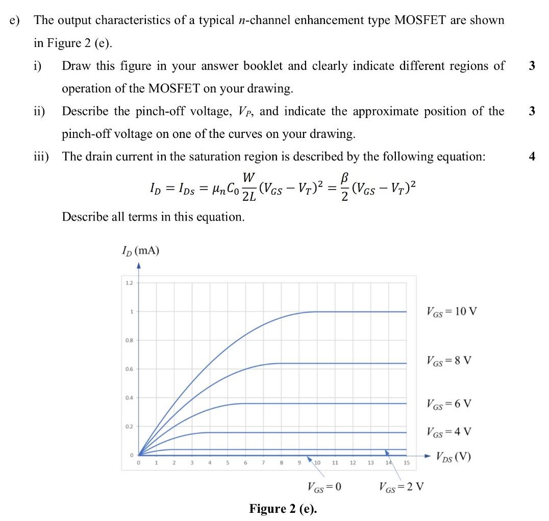
e) The output characteristics of a typical n-channel enhancement type MOSFET are shown in Figure 2 (e). i) Draw this figure in your answer booklet and clearly indicate different regions of 3 operation of the MOSFET on your drawing. ii) Describe the pinch-off voltage, VP, and indicate the approximate position of the 3 pinch-off voltage on one of the curves on your drawing. iii) The drain current in the saturation region is described by the following equation: 4 ID = IDs = μnC0W 2L(VGS−VT)2 = β 2(VGS−VT)2 Describe all terms in this equation. Figure 2 (e).

Image text
e) The output characteristics of a typical n -channel enhancement type MOSFET are shown in Figure 2 (e). i) Draw this figure in your answer booklet and clearly indicate different regions of 3 operation of the MOSFET on your drawing. ii) Describe the pinch-off voltage, V P , and indicate the approximate position of the 3 pinch-off voltage on one of the curves on your drawing. iii) The drain current in the saturation region is described by the following equation: 4
I D = I D s = μ n C 0 W 2 L ( V G S V T ) 2 = β 2 ( V G S V T ) 2
Describe all terms in this equation. Figure 2 (e).

Detailed Answer