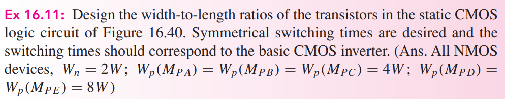
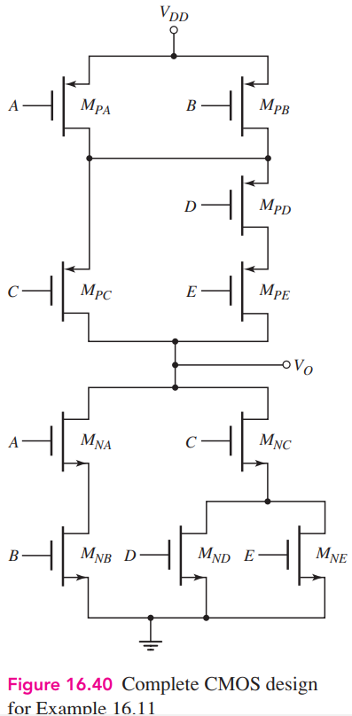
Ex 16.11: Design the width-to-length ratios of the transistors in the static CMOS logic circuit of Figure 16.40. Symmetrical switching times are desired and the switching times should correspond to the basic CMOS inverter. (Ans. All NMOS devices, Wn = 2W ; Wp(MPA) = Wp(MPB) = Wp(MPC) = 4W ; Wp(MPD) = Wp(MPE) = 8W )

You'll get a detailed, step-by-step and expert verified solution.
 Work With Experts to Reach at Correct Answers