Fig. 1. TSPC flip-flop with inverter added. 2) Use logical effort to size the transistors in the TSPC flip-flop shown in Fig. 1. Assume the output load capacitance is 20Cmin . Hint: The 1 st stage of the flip-flop does not affect the clk-to-Q delay. So, you can consider the constant for the first two stages of the flip-flop as 1. The figure below shows the critical path
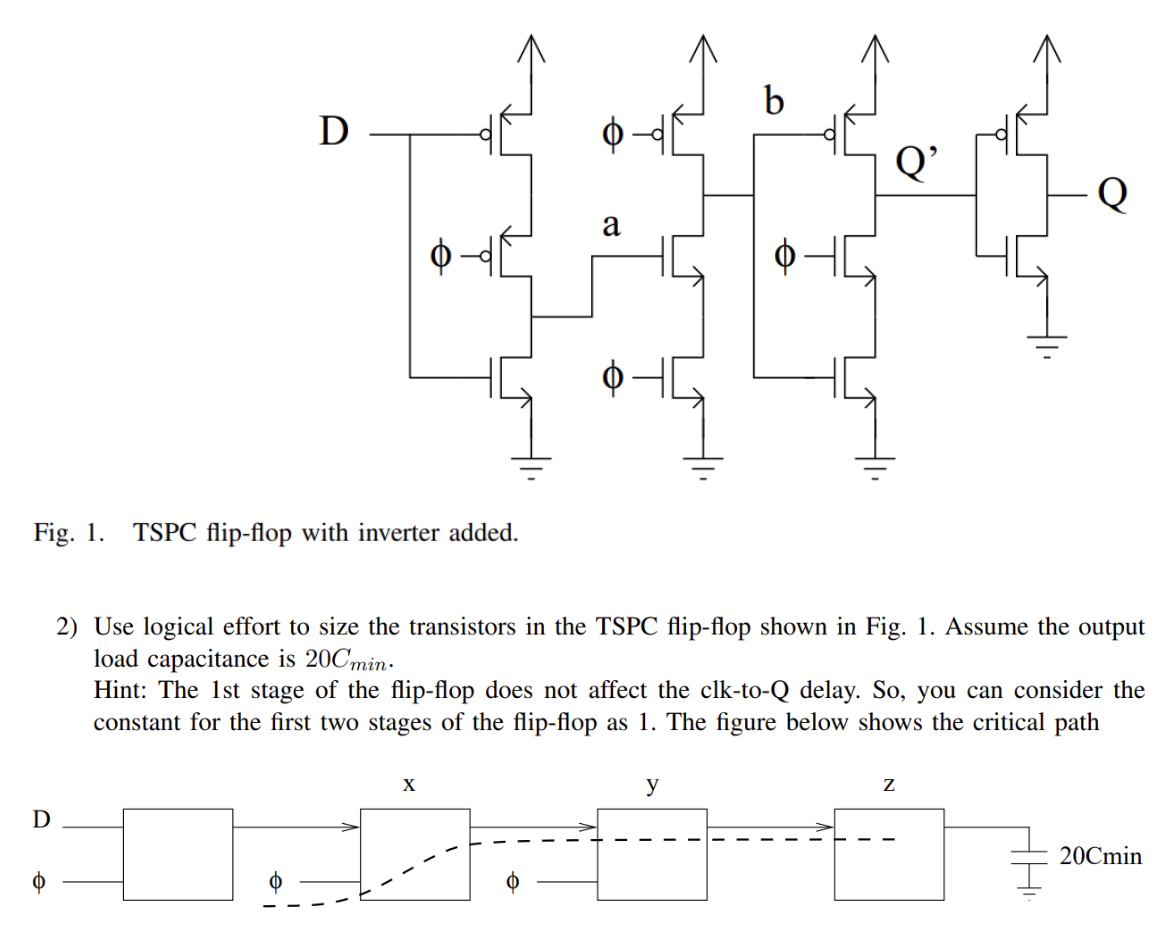
Fig. 1. TSPC flip-flop with inverter added. 2) Use logical effort to size the transistors in the TSPC flip-flop shown in Fig. 1. Assume the output load capacitance is 20Cmin . Hint: The 1 st stage of the flip-flop does not affect the clk-to-Q delay. So, you can consider the constant for the first two stages of the flip-flop as 1. The figure below shows the critical path

Image text
Fig. 1. TSPC flip-flop with inverter added. 2) Use logical effort to size the transistors in the TSPC flip-flop shown in Fig. 1. Assume the output load capacitance is 20 C min . Hint: The 1st stage of the flip-flop does not affect the clk-to-Q delay. So, you can consider the constant for the first two stages of the flip-flop as 1. The figure below shows the critical path

Detailed Answer