Fig. 13 (a) represents a source follower biased by an ideal current source I1. VDD = 3.3 V, gm1 = 2 mA/V,RL = 1 kΩ, CC = 10 nF (a) Determine the corner frequency (Hz) of the HPF characteristic of the transfer function of the amplifier. (b) Let's suppose the input of Fig. 13(b) is applied. Plot Vout (t). Specify Vout at t = 0+, 10 μs, and 20 μs in the plot.
Image text
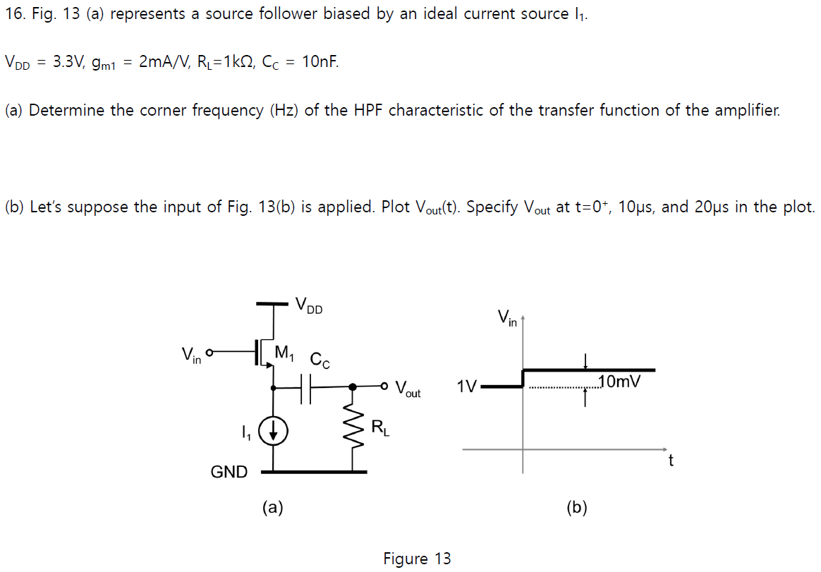
Fig. 13 (a) represents a source follower biased by an ideal current source I1. VDD = 3.3 V, gm1 = 2 mA/V,RL = 1 kΩ, CC = 10 nF (a) Determine the corner frequency (Hz) of the HPF characteristic of the transfer function of the amplifier. (b) Let's suppose the input of Fig. 13(b) is applied. Plot Vout (t). Specify Vout at t = 0+, 10 μs, and 20 μs in the plot.

![In Fig. 11, gm1 = 100uA/V, gm2 = 20uA/V, CL = 1pF. Ignore other parasitic capacitances. (a) Determine the transfer function Vout /Vin (s). (10) (b) Let's suppose that for a dc input of Vin = 1 V, Vout = 2 V. If Vin(t) = 1[V] + 1[mV]u(t), where u(t) is a unit step function at t = 0, determine Vout (t). (10)](https://www.doubtrix.com/js/ckeditor/filemanager/connectors/php/editor/1697810445-Adfekffuehf.png)

![In Fig. 5, VDD = 2.5 V, VB1 = 1 V, RG = 100 kΩ, RD = 10 kΩ, R1 = 10 kΩ, (W/L)1 = (W/L)2 = (W/L)3 = (W/L)4 = (1/0.1). CC1∼CC3 are very large. (a) Determine the VB2 such that the output (Vout) swing is maximized while all MOSFETs operate in the saturation region. (b) For a dc input of Vin = 1 V, determine Vx, Vz and Vout. Fig. 5 (c) When Vin(t) = 1[V] + 10[mV]sin(ωt) is applied, determine Vout(t). (10)](https://www.doubtrix.com/uploads/editor/3770622967fpfOfEpcYQ.jpg)