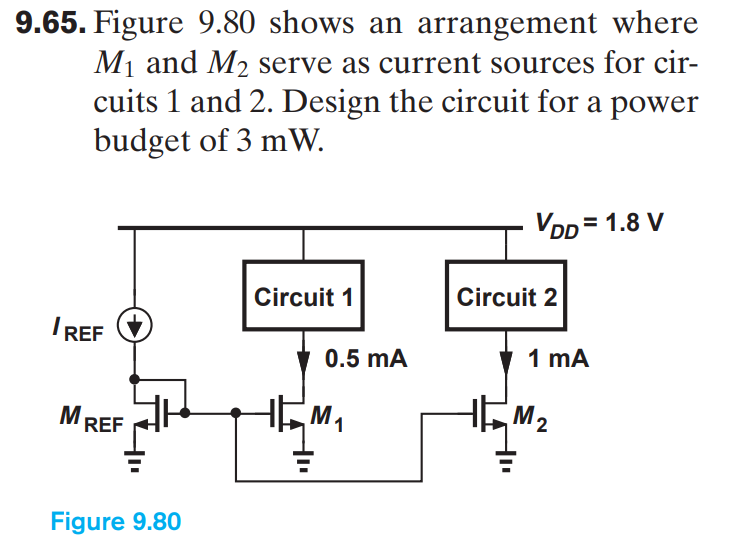
Figure 9.80 shows an arrangement where M1 and M2 serve as current sources for circuits 1 and 2. Design the circuit for a power budget of 3 mW. Figure 9.77 shows an arrangement where M1 and M2 serve as current sources for circuits 1 and 2. Design the circuit for a power budget of 3 mW. Figure 2 shows an arrangement where M1 and M2 serve as current sources for circuits 1 and 2. Design the circuit (that is, find suitable values of IREF and W/L ratio of the 3 MOSFETs) for a power budget of 3 mW.


You'll get a detailed, step-by-step and expert verified solution.
 Work With Experts to Reach at Correct Answers