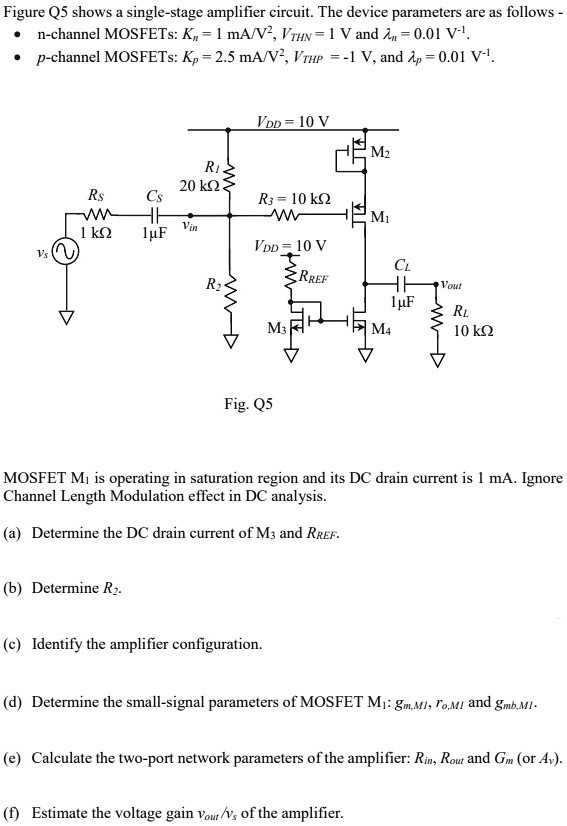
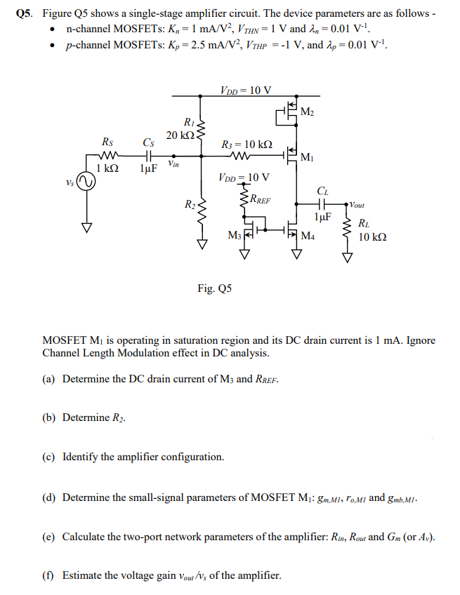
Figure Q5 shows a single-stage amplifier circuit. The device parameters are as follows -n-channel MOSFETs: Kn = 1 mA/V2, VTHN = 1 V and λn = 0.01 V−1. p-channel MOSFETs: Kp = 2.5 mA/V2, VTHP = −1 V, and λp = 0.01 V−1. Fig. Q5 MOSFET M1 is operating in saturation region and its DC drain current is 1 mA. Ignore Channel Length Modulation effect in DC analysis. (a) Determine the DC drain current of M3 and RREF. (b) Determine R2. (c) Identify the amplifier configuration. (d) Determine the small-signal parameters of MOSFET M1:gm,M1, ro, M1 and gmb,M1. (e) Calculate the two-port network parameters of the amplifier: Rin, Rout and Gm (or Av). (f) Estimate the voltage gain vout /vs of the amplifier.