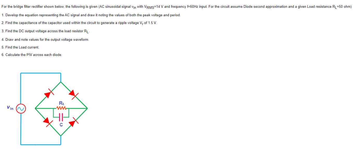
For the bridge filter rectifier shown below, the following is given ( AC sinusoidal signal vin with VRMS = 14 V and frequency f = 60 Hz input. For the circuit assume Diode second approximation and a given Load resistance RL = 50 ohm) Develop the equation representing the AC signal and draw it noting the values of both the peak voltage and period. Find the capacitance of the capacitor used within the circuit to generate a ripple voltage Vr of 1.5 V. Find the DC output voltage across the load resistor RL. Draw and note values for the output voltage waveform. Find the Load current. Calculate the PIV across each diode.

![Consider the full-wave diode rectifier circuit shown in the figure below. Assuming the input voltage is VAC = 170 sin(120πt) the conduction angle of the diode is 32∘, and the load resistance RL = 500 Ω, and the capacitor CS = 100 μF. We assume that all components are ideal and neglect the voltage drop across the diodes. {For the questions below, please only state the value. No need to include the units in your answers}. (a) Estimate the peak-to-peak ripple voltage in the output voltage VR. [2 marks] (b) The average voltage. [2 marks] (c) The RMS voltage. [2 marks] (d) The form factor. [2 marks] (e) If the ripple voltage across the load resistance RL must not exceed 1 V peak to-peak, calculate the value of smoothing capacitance required. You may assume that the capacitor provides current to the load for each complete cycle of the rectified voltage. [4 marks]](https://www.doubtrix.com/uploads/editor/0294629005gsMjwksRCG.jpg)