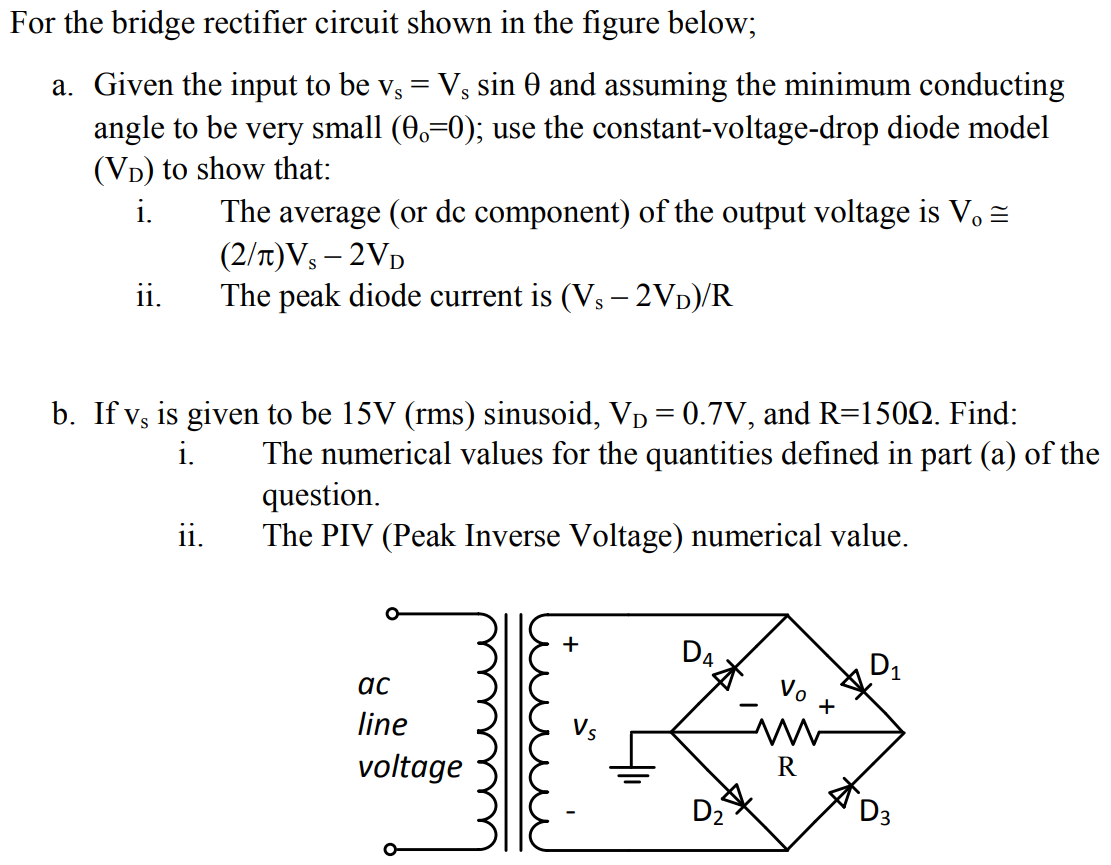
For the bridge rectifier circuit shown in the figure below; a. Given the input to be vs = Vssinθ and assuming the minimum conducting angle to be very small (θ0 = 0); use the constant-voltage-drop diode model (VD) to show that: i. The average (or dc component) of the output voltage is Vo≅ (2/π)Vs − 2VD ii. The peak diode current is (Vs − 2VD)/R b. If vs is given to be 15 V (rms) sinusoid, VD = 0.7 V, and R = 150 Ω. Find: i. The numerical values for the quantities defined in part (a) of the question. ii. The PIV (Peak Inverse Voltage) numerical value.

![(a) Assume that the MOSFET in Figure 3.1 is operating in saturation and is characterised by a threshold voltage, VT = 1 V. Assume that the parameter, K = 1 mA/V2 where the drain-source current in the MOSFET in saturation is given by the usual expression: iDS = K2(vGS−VT)2 Calculate the output voltage, vo, for the circuit shown in Figure 3.1 when vIN = 2.5 V, Vs = 10 V, and R = 1 kΩ. The correct solution should satisfy both conditions necessary for the device to operate in saturation. Figure 2.1 [10 marks] (b) For the circuit in Figure 2.1, calculate the small signal voltage gain of the circuit, Av, at the operating point defined by the numerical values of part (a). Assume the input and output voltages include small signal components, vin and vout respectively. VIN and Vout correspond to the constant DC components of the input and output voltage from part (a). vIN = VIN +vin vOUT = VOUT +vout Av = vout vin [10 marks] (c) Determine the small signal output impedance at the terminals labelled a and b for the circuit shown in Figure 3.1 and at the operating point defined by the numerical values of part (a). [10 marks]](https://www.doubtrix.com/uploads/editor/3475428305cJOidAHSIp.jpg)