For the circuit of the figure shown below, given that Vm = 9.8 V, R1 = 7.2 Ω, R2 = 13.5 Ω, ZL1 = j5.3 Ω, ZL2 = j18 Ω, ZM = j5.7 Ω and ZC = −j24 Ω, then the mesh equation (2) is: a. −j5.7 I1 + (13.5 − j42.0) I2 = 0 b. -j5.3 I1 + (13.5 - j6.0) I2 = 0 c. j5.3 I1 + (13.5 + j6.0) I2 = 0 d. -j5.7 I1 + (13.5 − j6.0) I2 = 0 e. j5.7 I1 + (13.5 − j6.0) I2 = 0
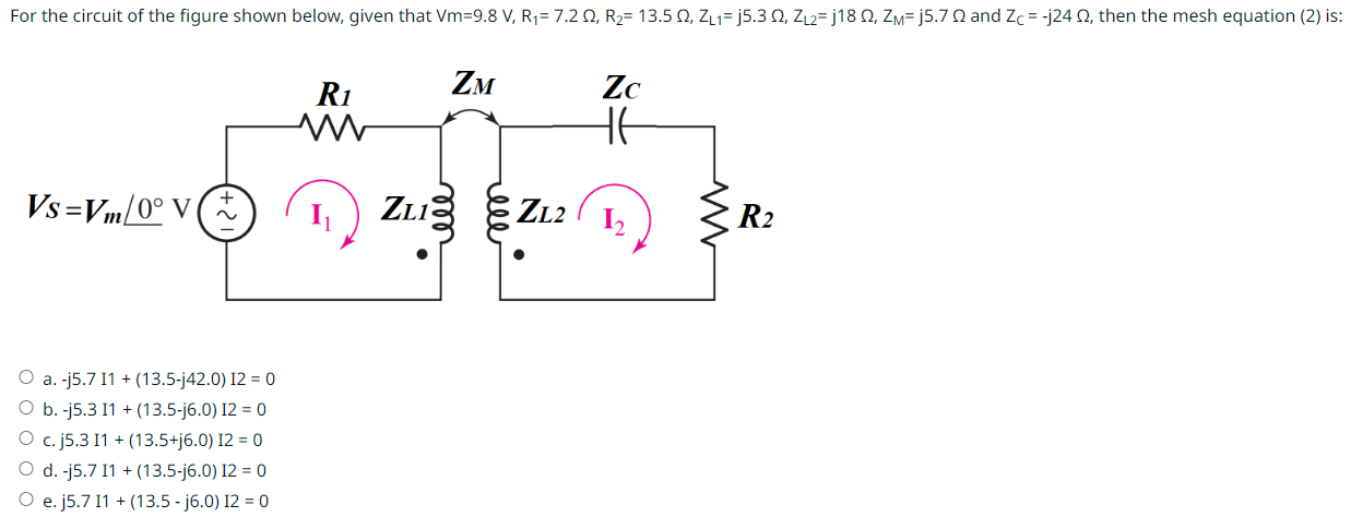
For the circuit of the figure shown below, given that Vm = 9.8 V, R1 = 7.2 Ω, R2 = 13.5 Ω, ZL1 = j5.3 Ω, ZL2 = j18 Ω, ZM = j5.7 Ω and ZC = −j24 Ω, then the mesh equation (2) is: a. −j5.7 I1 + (13.5 − j42.0) I2 = 0 b. -j5.3 I1 + (13.5 - j6.0) I2 = 0 c. j5.3 I1 + (13.5 + j6.0) I2 = 0 d. -j5.7 I1 + (13.5 − j6.0) I2 = 0 e. j5.7 I1 + (13.5 − j6.0) I2 = 0

Image text
For the circuit of the figure shown below, given that V m = 9.8 V , R 1 = 7.2 Ω , R 2 = 13.5 Ω , Z L 1 = j 5.3 Ω , Z L 2 = j 18 Ω , Z M = j 5.7 Ω and Z C = j 24 Ω , then the mesh equation (2) is: a. j 5.7 I 1 + ( 13.5 j 42.0 ) I 2 = 0 b. -j5.3 I1 + (13.5-j6.0) I2 = 0 c. j 5.3 I 1 + ( 13.5 + j 6.0 ) I 2 = 0 d. -j5.7 I1 + ( 13.5 j 6.0 ) I 2 = 0 e. j 5.7 I 1 + ( 13.5 j 6.0 ) I 2 = 0

Detailed Answer