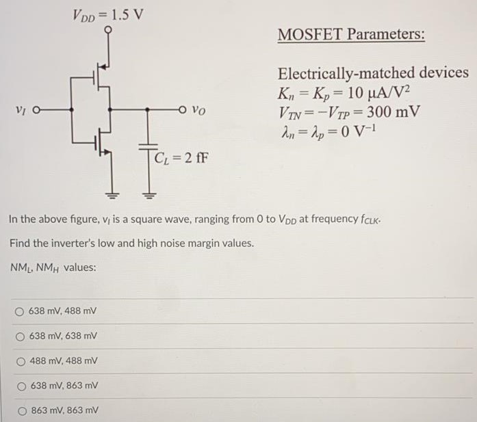
In the above figure, vI is a square wave, ranging from 0 to VDD at frequency fCLK. Find the inverter’s low and high noise margin values. NML, NMH values: 638 mV, 488 mV 638 mV, 638 mV 488 mV, 488 mV 638 mV, 863 mV 863 mV, 863 mV MOSFET Parameters: Electrically-matched devices Kn = Kp = 10 µA/V2 VTN = -VTP = 300 mV λn = λp = 0 V-1
Image text
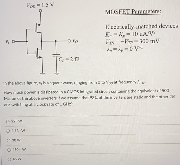
In the above figure, vI is a square wave, ranging from 0 to VDD at frequency fCLK. Find the inverter’s low and high noise margin values. NML, NMH values: 638 mV, 488 mV 638 mV, 638 mV 488 mV, 488 mV 638 mV, 863 mV 863 mV, 863 mV MOSFET Parameters: Electrically-matched devices Kn = Kp = 10 µA/V2 VTN = -VTP = 300 mV λn = λp = 0 V-1