In the circuit below, the operational amplifier is ideal, R1 = R3 = 10 kΩ, R2 = 100 kΩ and E = 4.3 V. The two diodes have the current-voltage characteristic shown by the plot on the right. For −1 V ≤ Vi ≤ 1 V, a) plot Vo as a function of Vi, b) plot Vo′ as a function of Vi. Assuming vi(t) is a sinusoidal signal with an amplitude of 1 V, c) plot vo(t), (2) d) plot vo′(t). (1)
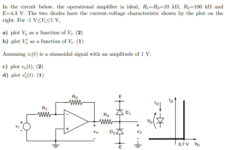
In the circuit below, the operational amplifier is ideal, R1 = R3 = 10 kΩ, R2 = 100 kΩ and E = 4.3 V. The two diodes have the current-voltage characteristic shown by the plot on the right. For −1 V ≤ Vi ≤ 1 V, a) plot Vo as a function of Vi, b) plot Vo′ as a function of Vi. Assuming vi(t) is a sinusoidal signal with an amplitude of 1 V, c) plot vo(t), (2) d) plot vo′(t). (1)

Image text
In the circuit below, the operational amplifier is ideal, R 1 = R 3 = 10 k Ω , R 2 = 100 k Ω and E = 4.3 V . The two diodes have the current-voltage characteristic shown by the plot on the right. For 1 V V i 1 V , a) plot V o as a function of V i , b) plot V o as a function of V i .
Assuming v i ( t ) is a sinusoidal signal with an amplitude of 1 V , c) plot v o ( t ) , ( 2 ) d) plot v o ( t ) . (1)

Detailed Answer