In the circuit shown in Figure 2. f, the transistor is biased in the saturation region. The transistor is an n-channel enhancement type MOSFET with an aspect ratio of (W/L) 15 , a threshold voltage of 2 V, and a gate capacitance per unit area of 480 nF/cm2. The electron mobility is 520 cm2/Vs. The bias parameters are VDD = 5 V, RD = 2.2 kΩ, R1 = 10 MΩ, and R2 = 12 MΩ. Calculate VGS, VDS, and ID at the operating
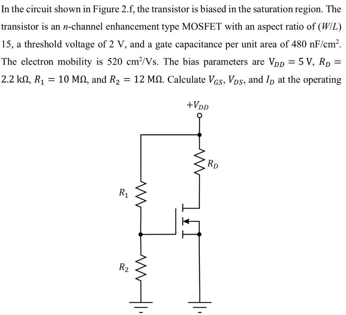
In the circuit shown in Figure 2. f, the transistor is biased in the saturation region. The transistor is an n-channel enhancement type MOSFET with an aspect ratio of (W/L) 15 , a threshold voltage of 2 V, and a gate capacitance per unit area of 480 nF/cm2. The electron mobility is 520 cm2/Vs. The bias parameters are VDD = 5 V, RD = 2.2 kΩ, R1 = 10 MΩ, and R2 = 12 MΩ. Calculate VGS, VDS, and ID at the operating

Image text
In the circuit shown in Figure 2.f, the transistor is biased in the saturation region. The transistor is an n -channel enhancement type MOSFET with an aspect ratio of (W/L) 15 , a threshold voltage of 2 V , and a gate capacitance per unit area of 480 n F / c m 2 . The electron mobility is 520 c m 2 / V s . The bias parameters are V D D = 5 V , R D = 2.2 k Ω , R 1 = 10 M Ω , and R 2 = 12 M Ω . Calculate V G S , V D S , and I D at the operating

Detailed Answer