In the following CMOS inverter, the threshold voltages of the n- and p-channel transistors are VTn and −|VTp|, respectively: a) Draw the input to output voltage transfer characteristic (VTC) for this inverter. Express and label clearly all voltage levels on the VTC plot. (20 points) b) Indicate the noise margins NML and NMH on the VTC. c) Indicate the logic high and low output voltage levels VOH, VOL on the VTC. d) Indicate the logic high and low input voltage levels VIH, VIL on the VTC. e) Indicate clearly the mode of operation in each region of the VTC.
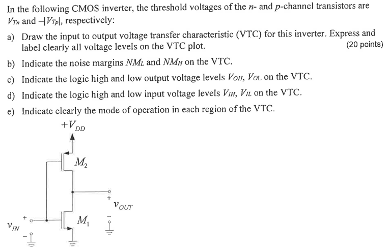
In the following CMOS inverter, the threshold voltages of the n- and p-channel transistors are VTn and −|VTp|, respectively: a) Draw the input to output voltage transfer characteristic (VTC) for this inverter. Express and label clearly all voltage levels on the VTC plot. (20 points) b) Indicate the noise margins NML and NMH on the VTC. c) Indicate the logic high and low output voltage levels VOH, VOL on the VTC. d) Indicate the logic high and low input voltage levels VIH, VIL on the VTC. e) Indicate clearly the mode of operation in each region of the VTC.

Image text
In the following CMOS inverter, the threshold voltages of the n - and p -channel transistors are V T n and | V T p | , respectively: a) Draw the input to output voltage transfer characteristic (VTC) for this inverter. Express and label clearly all voltage levels on the VTC plot. (20 points) b) Indicate the noise margins N M L and N M H on the VTC. c) Indicate the logic high and low output voltage levels V O H , V O L on the VTC. d) Indicate the logic high and low input voltage levels V I H , V I L on the VTC. e) Indicate clearly the mode of operation in each region of the VTC.

Detailed Answer