Problem 1: An n-channel enhancement-mode MOSFET with parameters VTR = 2 V and K = 1 mA/V2 is connected to the circuit below with VDD = 10 V and RD = 1 kΩ. (a) Plot the v−i characteristics of the MOSFET for VTR < VGS < 8 and 0 ≤ VDS ≤ 10 V. (b) Draw the load line imposed by VDD and RD over this set of v−I characteristics. (c) Graphically determine the transfer characteristic of the inverter over the range 0 < vIN < 8 V.
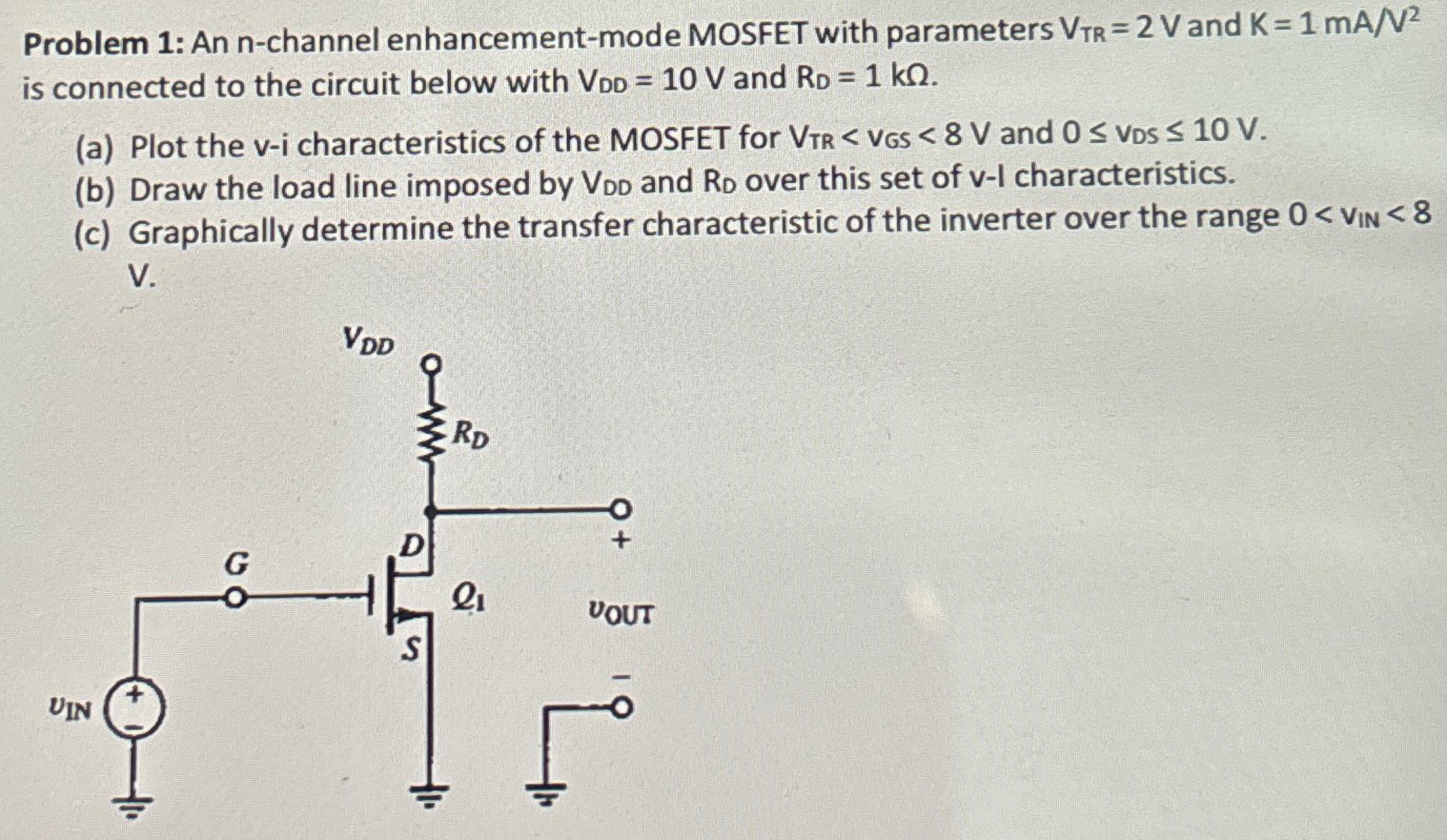
Problem 1: An n-channel enhancement-mode MOSFET with parameters VTR = 2 V and K = 1 mA/V2 is connected to the circuit below with VDD = 10 V and RD = 1 kΩ. (a) Plot the v−i characteristics of the MOSFET for VTR < VGS < 8 and 0 ≤ VDS ≤ 10 V. (b) Draw the load line imposed by VDD and RD over this set of v−I characteristics. (c) Graphically determine the transfer characteristic of the inverter over the range 0 < vIN < 8 V.

Image text
Problem 1: An n-channel enhancement-mode MOSFET with parameters V T R = 2 V and K = 1 m A / V 2 is connected to the circuit below with V D D = 10 V and R D = 1 k Ω . (a) Plot the v i characteristics of the MOSFET for V T R < V G S < 8 and 0 V D S 10 V . (b) Draw the load line imposed by V D D and R D over this set of v I characteristics. (c) Graphically determine the transfer characteristic of the inverter over the range 0 < v IN < 8 v.

Detailed Answer