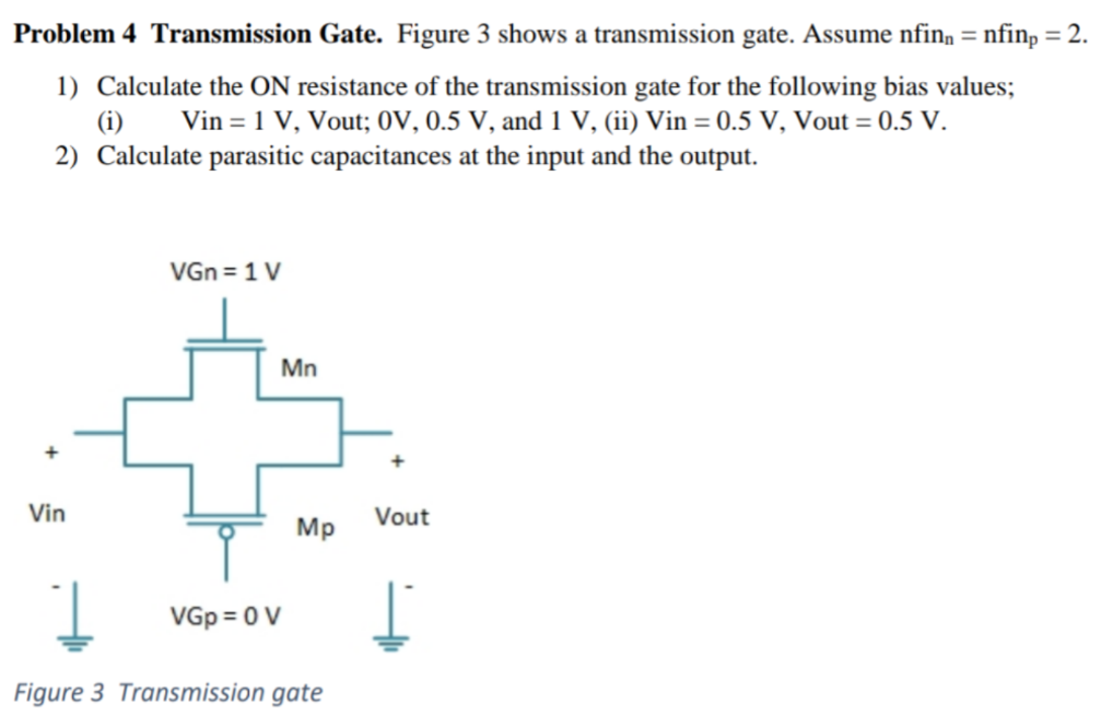
Problem 4 Transmission Gate. Figure 3 shows a transmission gate. Assume nfinn = nfinp = 2. Calculate the ON resistance of the transmission gate for the following bias values; (i) Vin = 1 V, Vout; 0 V, 0.5 V, and 1 V, (ii) Vin = 0.5 V, Vout = 0.5 V. Calculate parasitic capacitances at the input and the output. Figure 3 Transmission gate
Problem 4 Transmission Gate. Figure 3 shows a transmission gate. Assume nfinn = nfinp = 2. Calculate the ON resistance of the transmission gate for the following bias values; (i) Vin = 1 V, Vout; 0 V, 0.5 V, and 1 V, (ii) Vin = 0.5 V, Vout = 0.5 V. Calculate parasitic capacitances at the input and the output. Figure 3 Transmission gate

Image text
Problem 4 Transmission Gate. Figure 3 shows a transmission gate. Assume n f i n n = n f i n p = 2 .
  1. Calculate the O N resistance of the transmission gate for the following bias values; (i) V i n = 1 V , Vout; 0 V , 0.5 V , and 1 V , (ii) V i n = 0.5 V , Vout = 0.5 V .
  2. Calculate parasitic capacitances at the input and the output.
Figure 3 Transmission gate

Detailed Answer