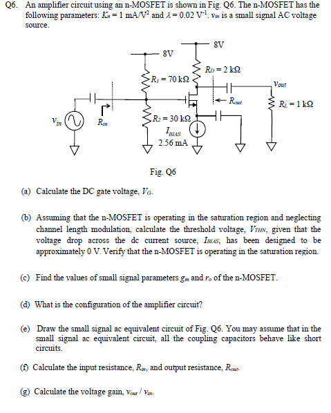
Q6. An amplifier circuit using an n-MOSFET is shown in Fig. Q6. The n-MOSFET has the following parameters: Kn = 1 mA/V2 and λ = 0.02 V−1. vin is a small signal AC voltage source. Fig. Q6 (a) Calculate the DC gate voltage, VG. (b) Assuming that the n-MOSFET is operating in the saturation region and neglecting channel length modulation, calculate the threshold voltage, VTHN, given that the voltage drop across the dc current source, IBUS, has been designed to be approximately 0 V. Verify that the n-MOSFET is operating in the saturation region. (c) Find the values of small signal parameters gm and ro of the n-MOSFET. (d) What is the configuration of the amplifier circuit? (e) Draw the small signal ac equivalent circuit of Fig. Q6. You may assume that in the small signal ac equivalent circuit, all the coupling capacitors behave like short circuits. (f) Calculate the input resistance, Rin, and output resistance, Rout . (g) Calculate the voltage gain, vout/vin.

![Q6. For the amplifier circuit shown in Fig. Q6, the MOS Transistor Ml has the following parameters: Kn = 1 mAV−2, and VTHN = 1 V. MOS transistors M2 and M3 are identical and have the following parameters: Kp = 1 mAV−2, and VTHP = −1 V. Fig. Q6 (a) Perform the DC analysis of the amplifier circuit shown in Fig. Q6, and show that the DC gate voltage of Ml is 5 V. You need to explain briefly your answer. (b) Calculate the value of RS such that the drain current of MI is 4 mA. Verify that the Ml is operating in the saturation region. [ Ans: Rs = 0.5 kΩ] (c) Calculate the parameters, gm and ro, of the small-signal model of the transistor Ml. [Ans: gm, M1 = 4 mAV−1, and ro, M1 = ∞ ] (d) What is the configuration of this amplifier? (e) Calculate the values of Rin , and Rout . [Ans: Rin = 5 kΩ and Rout = 2 kΩ ] (f) Estimate the voltage gain, Av( = vout /vin ). [ Ans: AV = −1.78]](https://www.doubtrix.com/uploads/editor/9864219624emwVzDjyOi.png)