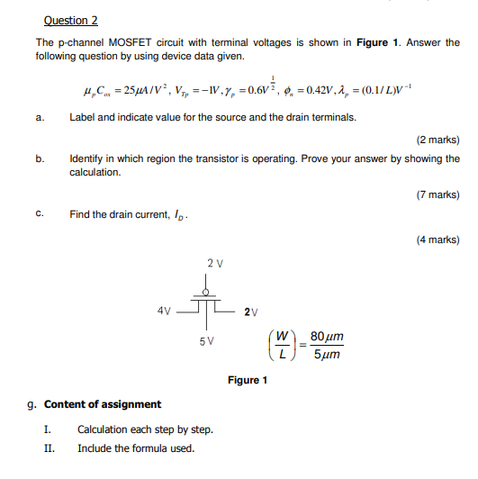
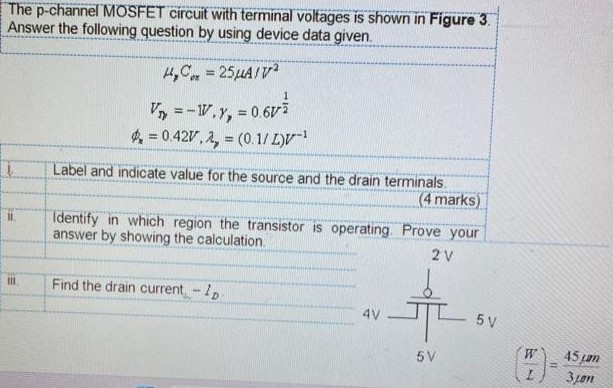
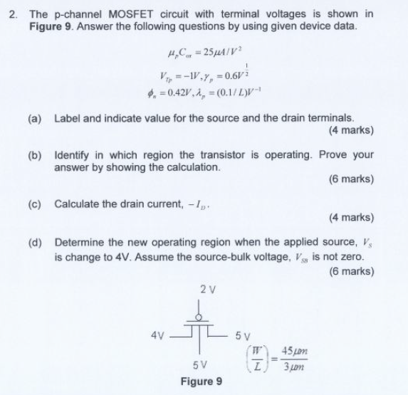
Question 2 The p-channel MOSFET circuit with terminal voltages is shown in Figure 1. Answer the following question by using device data given. μpCαt = 25 μA/V2, VTp = −1 V, γp = 0.6 V12, ϕn = 0.42 V, λp = (0.1/L)V−1 a. Label and indicate value for the source and the drain terminals. (2 marks) b. Identify in which region the transistor is operating. Prove your answer by showing the calculation. (7 marks) c. Find the drain current, ID. (4 marks) Figure 1 g. Content of assignment I. Calculation each step by step. II. Include the formula used.