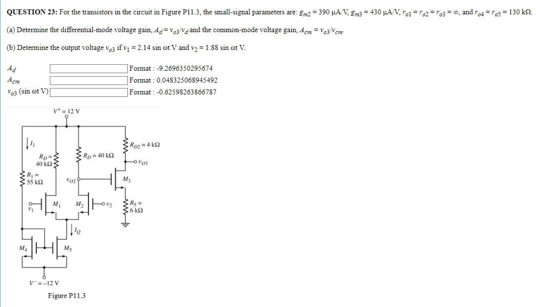
QUESTION 23: For the transistors in the circuit in Figure P11.3, the small-signal parameters are: gm2 = 390 μA/V, gm3 = 430 μA/V, ro1 = ro2 = ro3 = ∞, and ro4 = ro5 = 130 kΩ. (a) Determine the differential-mode voltage gain, Ad = vo3/vd and the common-mode voltage gain, Acm = vo3/vcm. (b) Determine the output voltage vo3 if v1 = 2.14 sin⁡ωt V and v2 = 1.88 sin⁡ωt V. Ad Format : -9.2696350295674 Acm Format : 0.048325068945492 vo3 (sin⁡ωt V) Format : -0.62598263866787 Figure P11.3
QUESTION 23: For the transistors in the circuit in Figure P11.3, the small-signal parameters are: gm2 = 390 μA/V, gm3 = 430 μA/V, ro1 = ro2 = ro3 = ∞, and ro4 = ro5 = 130 kΩ. (a) Determine the differential-mode voltage gain, Ad = vo3/vd and the common-mode voltage gain, Acm = vo3/vcm. (b) Determine the output voltage vo3 if v1 = 2.14 sin⁡ωt V and v2 = 1.88 sin⁡ωt V. Ad Format : -9.2696350295674 Acm Format : 0.048325068945492 vo3 (sin⁡ωt V) Format : -0.62598263866787 Figure P11.3

Image text
QUESTION 23: For the transistors in the circuit in Figure P11.3, the small-signal parameters are: g m 2 = 390 μ A / V , g m 3 = 430 μ A / V , r o 1 = r o 2 = r o 3 = , and r o 4 = r o 5 = 130 k Ω . (a) Determine the differential-mode voltage gain, A d = v o 3 / v d and the common-mode voltage gain, A c m = v o 3 / v c m . (b) Determine the output voltage v o 3 if v 1 = 2.14 sin ω t V and v 2 = 1.88 sin ω V V . A d Format : -9.2696350295674 A c m Format : 0.048325068945492 v o 3 ( sin ω t V ) Format : -0.62598263866787
Figure P11.3

Detailed Answer