Required information NOTE: This is a multi-part question. Once an answer is submitted, you will be unable to return to this part. The switch shown in the circuit below is moved from A to B at t = 0 after being at A for a long time. This places the two capacitors in series, thus allowing equal and opposite dc voltages to be trapped on the capacitors. If V = 150 V, find i(t). (You must provide an answer before moving on to the next part.) The expression of i(t) is Ae−t/B mA, where A = and B = ms.
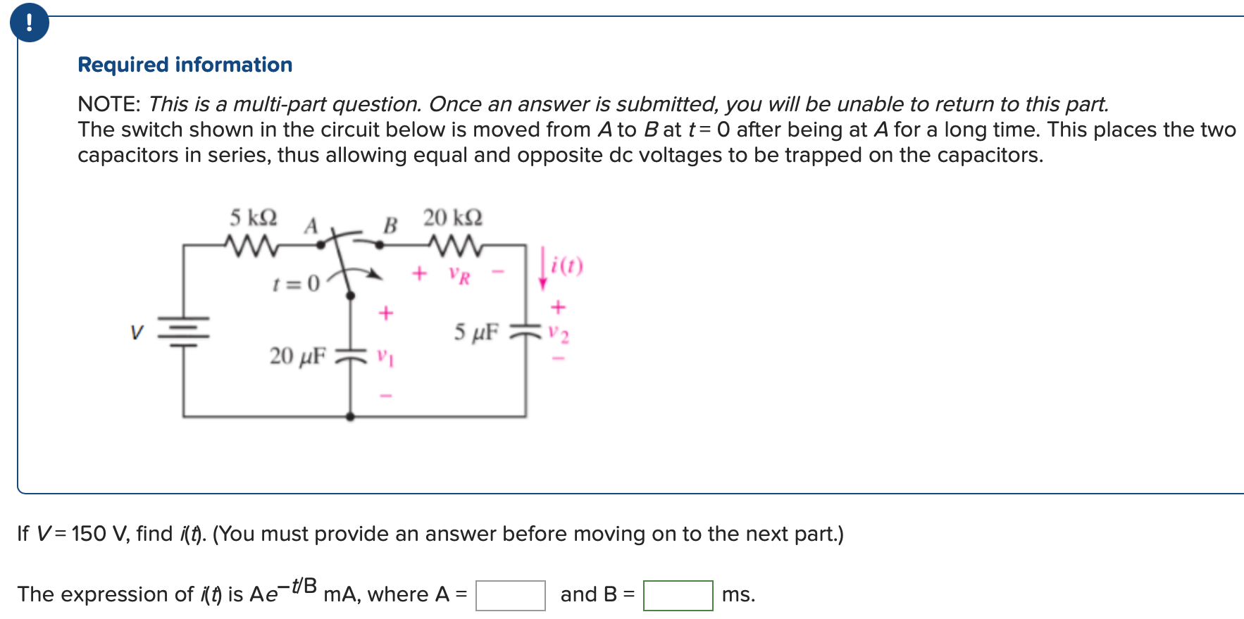
Required information NOTE: This is a multi-part question. Once an answer is submitted, you will be unable to return to this part. The switch shown in the circuit below is moved from A to B at t = 0 after being at A for a long time. This places the two capacitors in series, thus allowing equal and opposite dc voltages to be trapped on the capacitors. If V = 150 V, find i(t). (You must provide an answer before moving on to the next part.) The expression of i(t) is Ae−t/B mA, where A = and B = ms.

Image text
! Required information NOTE: This is a multi-part question. Once an answer is submitted, you will be unable to return to this part. The switch shown in the circuit below is moved from A to B at t = 0 after being at A for a long time. This places the two capacitors in series, thus allowing equal and opposite dc voltages to be trapped on the capacitors.
If V = 150 V , find i ( t ) . (You must provide an answer before moving on to the next part.) The expression of i ( t ) is A e t / B m A , where A = and B = ms.

Detailed Answer