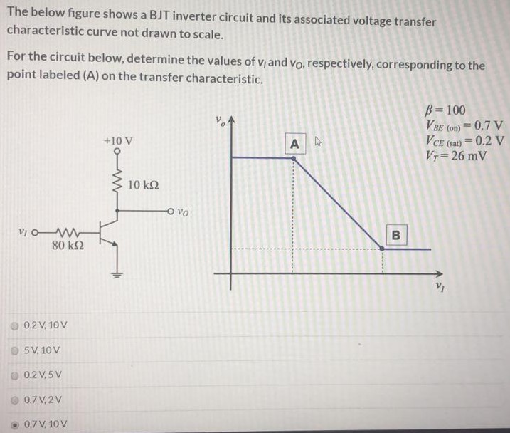
The below figure shows a BJT inverter circuit and its associated voltage transfer characteristic curve not drawn to scale. For the circuit below, determine the values of v1 and v0, respectively, corresponding to the point labeled (A) on the transfer characteristic. 0.2 V, 10 V 5 V, 10 V 0.2 V, 5 V 0.7 V, 2 V 0.7 V, 10 V
