The circuit below is a high-pass filter. The designer intends to obtain a high-frequency gain of 40 dB, a corner frequency w1 of 100 rad/sec, and an input impedance of ∼2.5 kΩ at high frequencies ( > > w1). a) Determine the values of C1, R1, and R2 to obtain the above specifications. b) Draft the Bode plot of the voltage gain, magnitude only.
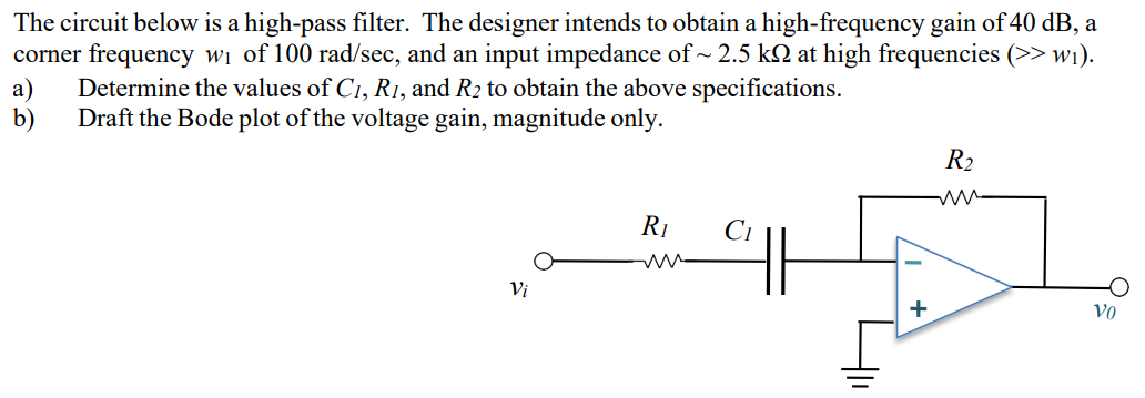
The circuit below is a high-pass filter. The designer intends to obtain a high-frequency gain of 40 dB, a corner frequency w1 of 100 rad/sec, and an input impedance of ∼2.5 kΩ at high frequencies ( > > w1). a) Determine the values of C1, R1, and R2 to obtain the above specifications. b) Draft the Bode plot of the voltage gain, magnitude only.

Image text
The circuit below is a high-pass filter. The designer intends to obtain a high-frequency gain of 40 d B , a corner frequency w 1 of 100 r a d / s e c , and an input impedance of 2.5 k Ω at high frequencies ( >> w 1 ) . a) Determine the values of C 1 , R 1 , and R 2 to obtain the above specifications. b) Draft the Bode plot of the voltage gain, magnitude only.

Detailed Answer