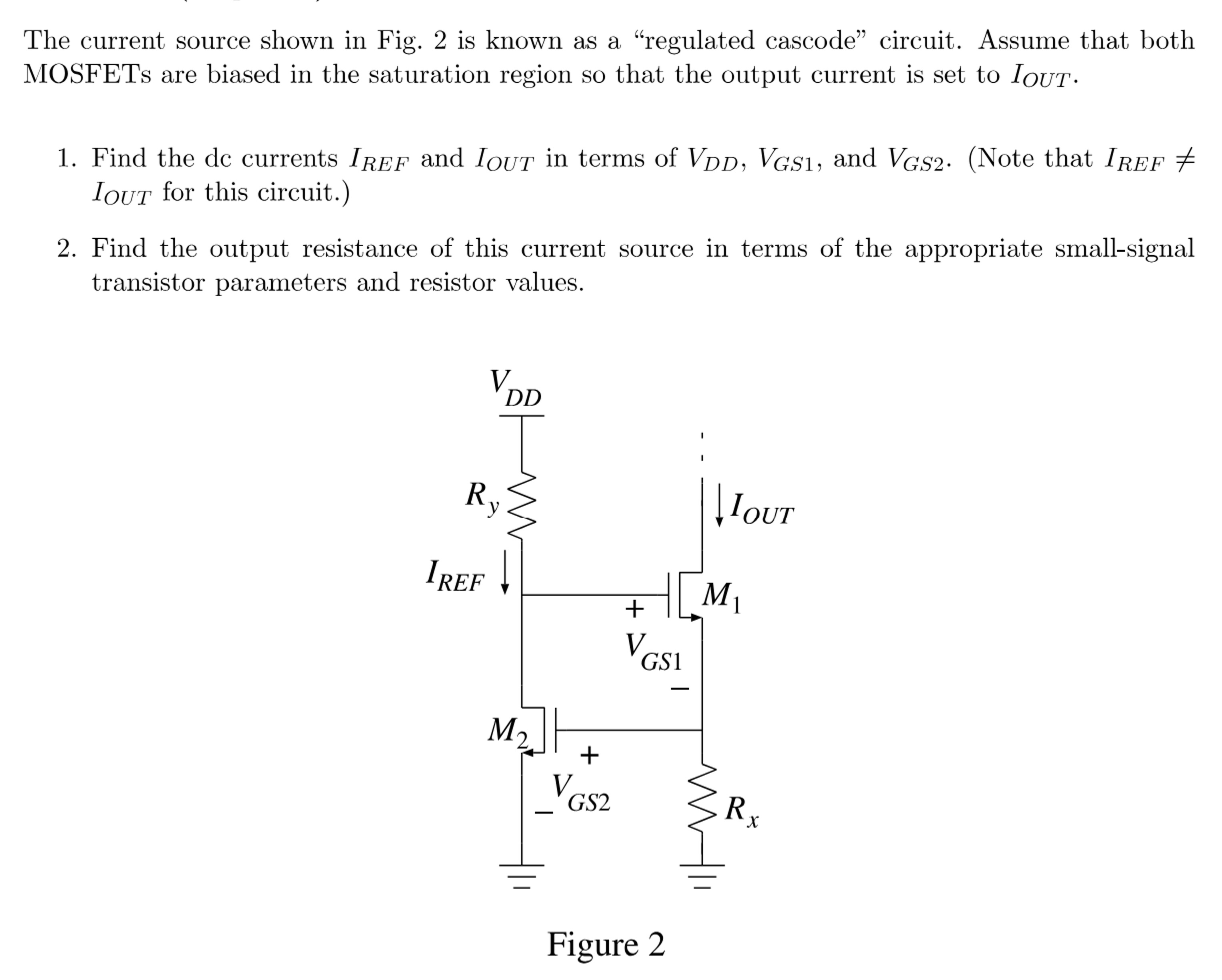
The current source shown in Fig. 2 is known as a "regulated cascode" circuit. Assume that both MOSFETs are biased in the saturation region so that the output current is set to IOUT. Find the dc currents IREF and IOUT in terms of VDD, VGS1, and VGS2. (Note that IREF ≠ IOUT for this circuit. )Find the output resistance of this current source in terms of the appropriate small-signal transistor parameters and resistor values. Figure 2