The differential amplifier depicted in the following figure employs two current mirrors to establish the bias for the input and load de-vices. Assume W/L = 10 μm/0.18 μm for M1 M6. The input CM level is equal to 1.2 V. (a) Select (W/L)7 so as to set the output CM level to 1.5 V. (Assume L7 = 0.18 μm.) (b) Determine the small-signal differential gain of the circuit. (c) Plot the differential input/output characteristic.
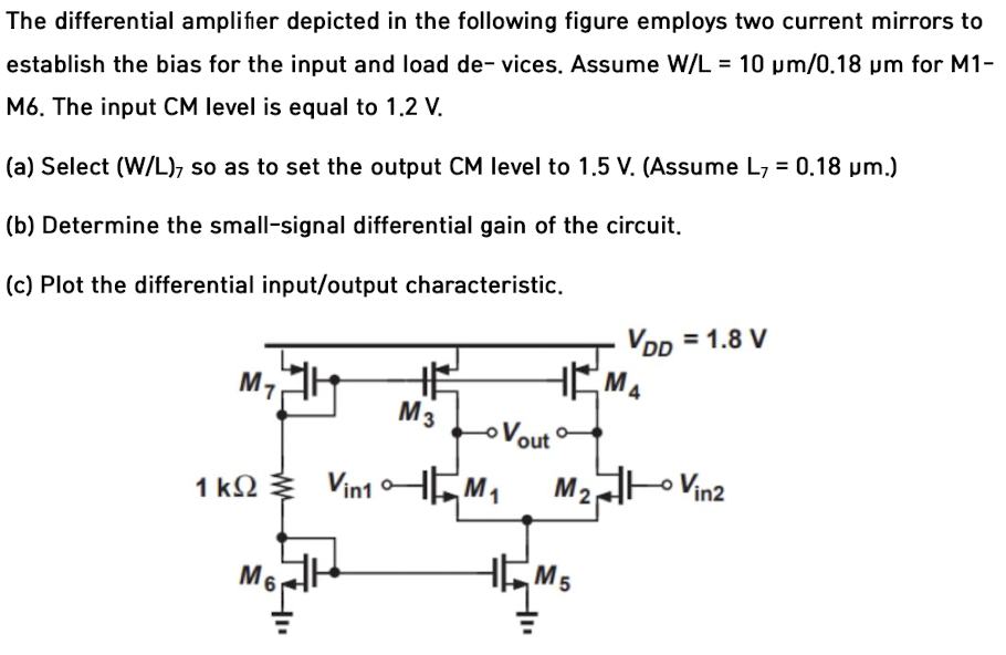
The differential amplifier depicted in the following figure employs two current mirrors to establish the bias for the input and load de-vices. Assume W/L = 10 μm/0.18 μm for M1 M6. The input CM level is equal to 1.2 V. (a) Select (W/L)7 so as to set the output CM level to 1.5 V. (Assume L7 = 0.18 μm.) (b) Determine the small-signal differential gain of the circuit. (c) Plot the differential input/output characteristic.

Image text
The differential amplifier depicted in the following figure employs two current mirrors to establish the bias for the input and load de-vices. Assume W/L = 10 μ m / 0.18 μ m for M1M6. The input CM level is equal to 1.2 V . (a) Select ( W / L ) 7 so as to set the output C M level to 1.5 V . (Assume L 7 = 0.18 μ m .) (b) Determine the small-signal differential gain of the circuit. (c) Plot the differential input/output characteristic.

Detailed Answer