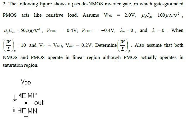
The following figure shows a pseudo-NMOS inverter gate, in which gate-grounded PMOS acts like resistive load. Assume VDD = 2.0V, unCox = 100 uA/V2, upCox = 50 uA/V2, VTHN = 0.4V, VTHP = -0.4V, lambda_n = 0, and lambda_p = 0. When (W/L)n =10 and Vin = VDD, Vout = 0.2V. Determine (W/L)p. Also assume that both NMOS and PMOS operate in linear region although PMOS actually operates in saturation region.
You'll get a detailed, step-by-step and expert verified solution.
 Work With Experts to Reach at Correct Answers