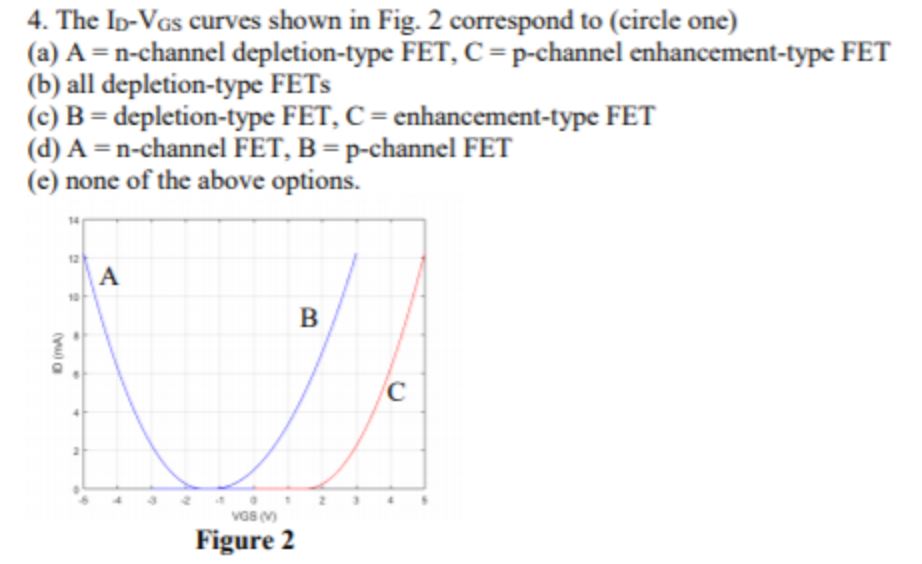
The ID-VGs curves shown in Fig. 2 correspond to (circle one) (a) A = n-channel depletion-type FET, C = p-channel enhancement-type FET (b) all depletion-type FETs (c) B = depletion-type FET, C = enhancement-type FET (d) A = n-channel FET, B = p-channel FET (e) none of the above options. Figure 2