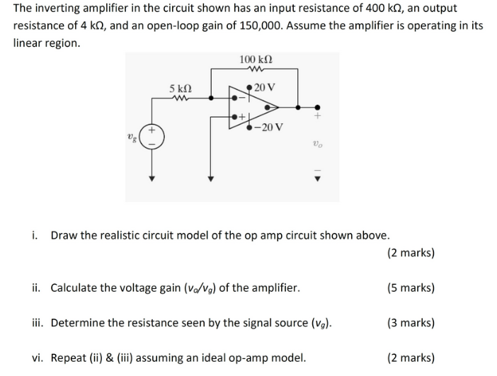
The inverting amplifier in the circuit shown has an input resistance of 400 kΩ, an output resistance of 4 kΩ, and an open-loop gain of 150,000 . Assume the amplifier is operating in its linear region. i. Draw the realistic circuit model of the op amp circuit shown above. (2 marks) ii. Calculate the voltage gain (vo/vg) of the amplifier. (5 marks) iii. Determine the resistance seen by the signal source (vg). (3 marks) vi. Repeat (ii) & (iii) assuming an ideal op-amp model. (2 marks)