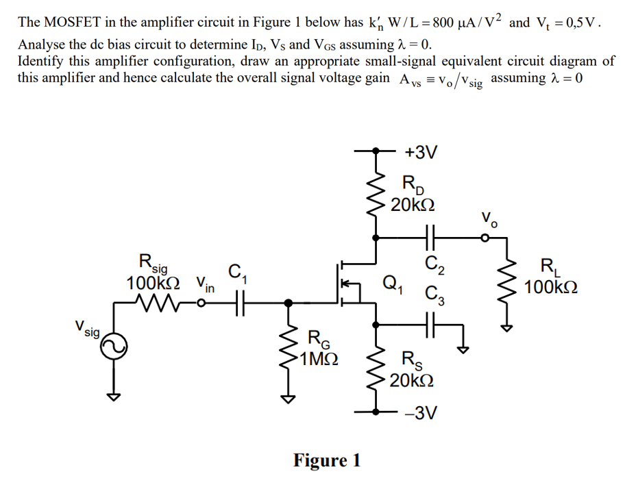
The MOSFET in the amplifier circuit in Figure 1 below has kn′W/L = 800 μA/V2 and Vt = 0,5 V. Analyse the dc bias circuit to determine ID, VS and VGS assuming λ = 0. Identify this amplifier configuration, draw an appropriate small-signal equivalent circuit diagram of this amplifier and hence calculate the overall signal voltage gain Avs = vo/vsig assuming λ = 0 Figure 1
The MOSFET in the amplifier circuit in Figure 1 below has kn′W/L = 800 μA/V2 and Vt = 0,5 V. Analyse the dc bias circuit to determine ID, VS and VGS assuming λ = 0. Identify this amplifier configuration, draw an appropriate small-signal equivalent circuit diagram of this amplifier and hence calculate the overall signal voltage gain Avs = vo/vsig assuming λ = 0 Figure 1

Image text
The MOSFET in the amplifier circuit in Figure 1 below has k n W / L = 800 μ A / V 2 and V t = 0 , 5 V . Analyse the dc bias circuit to determine I D , V S and V G S assuming λ = 0 . Identify this amplifier configuration, draw an appropriate small-signal equivalent circuit diagram of this amplifier and hence calculate the overall signal voltage gain A v s v o / v sig assuming λ = 0 Figure 1

Detailed Answer