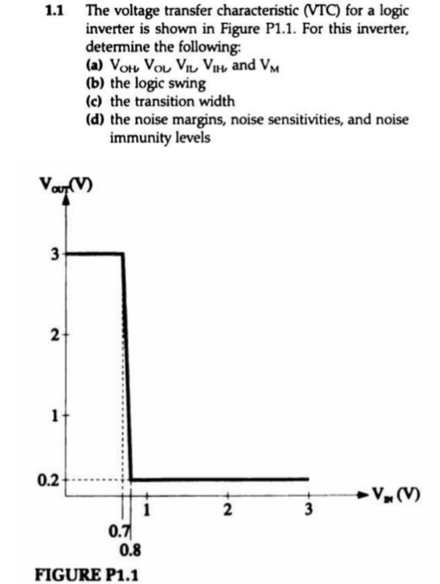
The voltage transfer characteristic (VTC) for a logic inverter is shown in Figure P1.1. For this inverter, determine the following: (a) VOH, VOL, VIL, VIH and VM (b) the logic swing (c) the transition width (d) the noise margins, noise sensitivities, and noise immunity levels


You'll get a detailed, step-by-step and expert verified solution.
 Work With Experts to Reach at Correct Answers