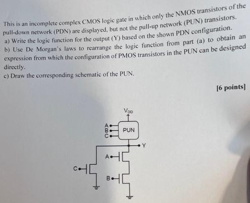
This is an incomplete complex CMOS logic gate in which only the NMOS transistors of the pull-down network (PDN) are displayed, but not the pull-up network (PUN) transistors. a) Write the logic function for the output (Y) based on the shown PDN configuration. b) Use De Morgan's laws to rearrange the logic function from expression from part (a) to obtain an expression which the configuration of PMOS transistors in the PUN can be designed directly. c) Draw the corresponding schematic of the PUN.
You'll get a detailed, step-by-step and expert verified solution.
 Work With Experts to Reach at Correct Answers