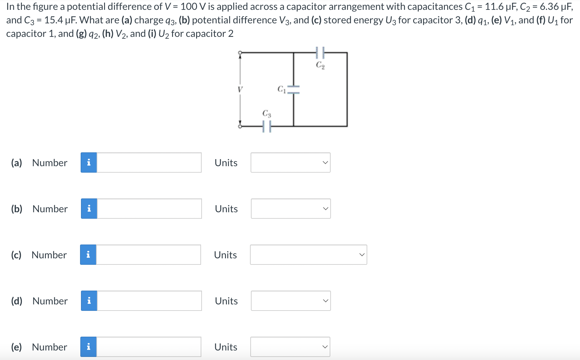
In the figure a potential difference of V = 100 V is applied across a capacitor arrangement with capacitances C1 = 11.6 μF, C2 = 6.36 μF, and C3 = 15.4 μF. What are (a) charge q3, (b) potential difference V3, and (c) stored energy U3 for capacitor 3, (d) q1, (e) V1, and (f) U1 for capacitor 1, and (g)q2, (h) V2, and (i) U2 for capacitor 2 (a) Number Units (b) Number Units (c) Number Units (d) Number Units (e) Number Units
